Nissan Altima HL32 Hybrid. Manual - part 667


  Index      Nissan     Nissan Altima HL32 Hybrid (2009 year) - Service and Repair Manual


Search            


Content   ..  665  666  667  668   ..


Nissan Altima HL32 Hybrid. Manual - part 667


P0AA4-232

HBC-417

< COMPONENT DIAGNOSIS >

D

E

F

G

H

I

J

K

L

M

A

B

HBC

N

O

P

DTC Logic

INFOID:0000000004212048

DTC DETECTION LOGIC

Diagnosis Procedure

INFOID:0000000004212049

1.

PRECONDITIONING

• Before inspecting the high-voltage system or disconnecting the low voltage connector of the inverter with

converter assembly, take safety precautions such as wearing insulated gloves and removing the service

plug grip to prevent electrical shocks. After removing the service plug grip, put it in your pocket to prevent

other technicians from accidentally reconnecting it while you are working on the high-voltage system.

• After disconnecting the service plug grip, wait for at least 10 minutes before touching any of the high-voltage

connectors or terminals.

• Waiting for at least 10 minutes is required to discharge the high-voltage capacitor inside the inverter with

converter assembly.

• If DTC P0AA4-232 is stored, the vehicle will not turn on.
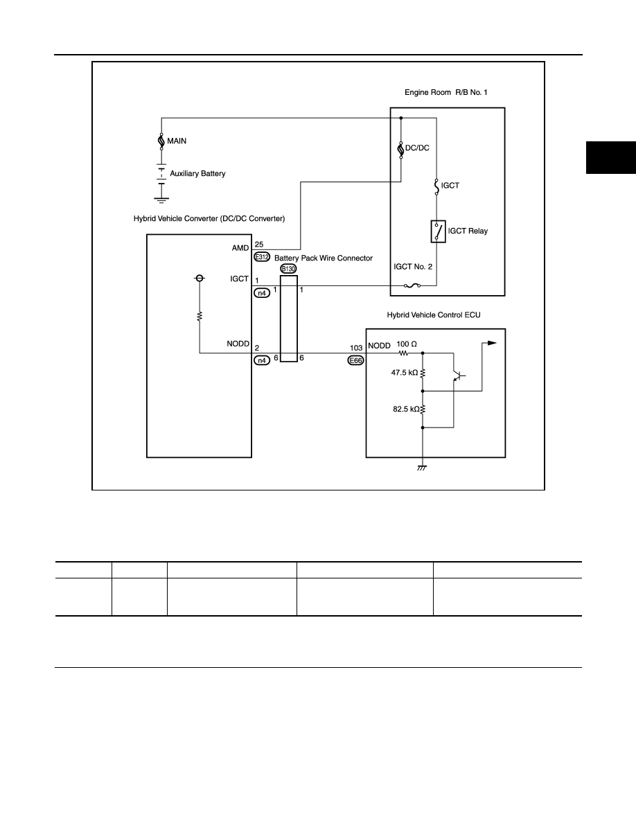
JMCIA0125GB

DTC No.

INF code

Trouble diagnosis name

DTC detecting condition

Possible cause

P0AA4

232

Hybrid Battery Negative Con-
tactor Circuit Stuck Closed

System main relay G on the HV 
battery negative side is stuck 
closed.

• HV relay assembly
• Inverter with converter assembly

HBC-418

< COMPONENT DIAGNOSIS >

P0AA4-232

>> GO TO 2.

2.

CHECK DTC OUTPUT

1. Turn ignition switch ON.

2. Check DTC.

Is DTC detected?

YES

>> Go to Diagnosis Procedure relevant to output DTC.

NO

>> GO TO 3.

3.

CHECK FREEZE FRAME DATA

1. Turn ignition switch ON.

2. Read output DTCs.

3. Read the freeze frame data of P0AA4-232.

A or B

A

>> Replace inverter with converter assembly (See 

HBC-638, "Removal and Installation"

).

B

>> GO  TO  4.

4.

CHECK HV RELAY ASSEMBLY

CAUTION:

Be sure to wear insulated gloves.

1. Turn ignition switch OFF and remove the service plug grip (See 

HBC-632, "Precautions for Inspecting the

Hybrid Control System"

).

NOTE:

After removing the service plug grip, do not turn ignition switch ON (READY), unless instructed by

the service manual because this may cause a malfunction.

DTC No. 

Relevant Part

P0A1A-156, 658, 659, 151, 155, 200, 791, 792, 793

Generator Control Module

P0A1A-156, 658, 659, 151, P0A1B-511, 164, 163, 512, 193, 786, 
788, 661, 192, 168, 794, 795, 796

Drive Motor "A" Control Module

P0A1F

Battery Energy Control Module

P0A3F-243

Drive Motor "A" Position Sensor Circuit

P0A40-500

Drive Motor "A" Position Sensor Circuit Range / Performance

P0A41-245

Drive Motor "A" Position Sensor Circuit Low

P0A4B-253

Generator Position Sensor Circuit

P0A4C-513

Generator Position Sensor Circuit Range / Performance

P0A4D-255

Generator Position Sensor Circuit Low

P0A78-266, 267, 523, 586, 503, 504, 279, 282, 284, 505, 287, 
506,286, 113, 306

Drive Motor "A" Inverter Performance

P0A7A-322, 517, 325, 518, 324, 122, 344

Generator Inverter Performance

P0A90-509

Drive Motor "A" Performance

P0A92-521

Hybrid Generator Performance

P0A94-442

DC/DC Converter Performance

P0AE0-228

Hybrid Battery Negative Contactor Control Circuit High

P0AE2-161, 773

Hybrid Battery Precharge Contactor Circuit Stuck Closed

P3004-132

HV Battery Malfunction

P3105

Battery Observation Communication Circuit Malfunction

Result

Proceed to

IB BATTERY (Current value of HV battery) is less than 3 A.

A

IB BATTERY (Current value of HV battery) is 3 A or more. 

B

P0AA4-232

HBC-419

< COMPONENT DIAGNOSIS >

D

E

F

G

H

I

J

K

L

M

A

B

HBC

N

O

P

2. Measure the resistance according to the value(s) in the table

below.

NOTE:

• For the removal and installation procedures related to inspec-

tion of the HV relay assembly, (See 

HBB-105, "Removal and

Installation"

).

• Leave the HV relay in the vehicle while testing to prevent the movement that occurs during removal from

causing a stuck relay to return to normal.

• If the result of reading the freeze frame data is B, the HV relay assembly must be replaced. Measuring

resistance can determine that this is either a present or past malfunction. 

OK or NG

OK

>> Replace inverter with converter assembly (See 

HBC-638, "Removal and Installation"

).

NG

>> Replace HV relay assembly (See 

HBB-105, "Removal and Installation"

).

HV Relay Assembly

HV Relay Assembly

Resistance 

Component 

connector

Terminal

Component 

connector

Terminal

E309

22

t1 1

10 

k

Ω or higher

JMCIA0199GB

HBC-420

< COMPONENT DIAGNOSIS >

P0AA6-526, P0AA6-611, P0AA6-612, P0AA6-613, P0AA6-614

P0AA6-526, P0AA6-611, P0AA6-612, P0AA6-613, P0AA6-614

Description

INFOID:0000000004212050

The hybrid vehicle control ECU monitors the battery smart unit and detects insulation malfunctions in the high-

voltage system.

DTC Logic

INFOID:0000000004212051

DTC DETECTION LOGIC

JMCIA0104GB


Content   ..  665  666  667  668   ..