Nissan Altima HL32 Hybrid. Manual - part 626


  Index      Nissan     Nissan Altima HL32 Hybrid (2009 year) - Service and Repair Manual


Search            


Content   ..  624  625  626  627   ..


Nissan Altima HL32 Hybrid. Manual - part 626


P0A78-284

HBC-253

< COMPONENT DIAGNOSIS >

D

E

F

G

H

I

J

K

L

M

A

B

HBC

N

O

P

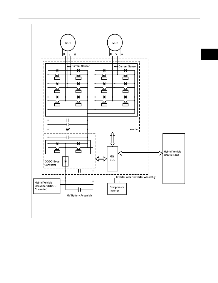
The MG ECU monitors the inverter voltage and detects malfunctions.

DTC Logic

INFOID:0000000004211925

DTC DETECTION LOGIC

If the motor inverter overheats, or has a circuit malfunction or internal short, the inverter transmits this informa-

tion to the MFIV terminal of the MG ECU via the motor inverter fail signal line.

If the motor inverter overheats, it transmits an inverter fail signal to the MG ECU. Upon receiving this signal,

the hybrid vehicle control ECU will illuminate the MIL and set a DTC.

JMCIA0099GB

HBC-254

< COMPONENT DIAGNOSIS >

P0A78-284

Diagnosis Procedure

INFOID:0000000004211926

1.

PRECONDITIONING

• Before inspecting the high-voltage system or disconnecting the low voltage connector of the inverter with

converter assembly, take safety precautions such as wearing insulated gloves and removing the service

plug grip to prevent electrical shocks. After removing the service plug grip, put it in your pocket to prevent

other technicians from accidentally reconnecting it while you are working on the high-voltage system.

• After disconnecting the service plug grip, wait for at least 10 minutes before touching any of the high-voltage

connectors or terminals.

• After inspection, be sure to replace the inverter with converter assembly.

• Waiting for at least 10 minutes is required to discharge the high-voltage capacitor inside the inverter with

converter assembly.

>> GO TO 2.

2.

CHECK DTC OUTPUT (HYBRID SYSTEM)

1. Turn ignition switch ON.

2. Check DTC.

NOTE:

DTC P0A78-284 may be set due to a malfunction which also causes DTCs in the table above to be set. 

DTC No.

INF Code

Trouble diagnosis name

DTC detecting condition

Possible cause

P0A78

284

Drive Motor “A” Inverter 
Performance

Motor inverter fail signal detection 
(overheat)

• Wire harness or connector
• Inverter cooling system
• Cooling fan system
• Water pump with motor & bracket as-

sembly

• Hybrid transaxle
• Inverter with converter assembly
• Hybrid vehicle control ECU

DTC No.

Relevant Diagnosis

P0A1D (Except INF code 390)

Hybrid Powertrain Control Module

P0A1A (all INF codes)

Generator Control Module

P0A1B (all INF codes)

Drive Motor “A” Control Module

P0A72 (all INF codes)

Generator Phase V Current

P0A75 (all INF codes)

Generator Phase W Current

P0A60 (all INF codes)

Drive Motor “A” Phase V Current

P0A63 (all INF codes)

Drive Motor “A” Phase W Current

P0A4B-253

Generator Position Sensor Circuit

P0A4D-255

Generator Position Sensor Circuit Low

P0A4C-513

Generator Position Sensor Circuit Range / Performance

P0A3F-243

Drive Motor “A” Position Sensor Circuit

P0A41-245

Drive Motor “A” Position Sensor Circuit Low

P0A40-500

Drive Motor “A” Position Sensor Circuit Range/Performance

P0A78-266, 267, 523, 586, 505, 287, 506, 503, 279, 504, 306, 
806, 807, 808

Drive Motor “A” Inverter Performance

P0A94-585, 587, 589, 590, 554, 555, 556, 547, 548, 549, 442 DC/DC Converter Performance

P0A7A-517, 325, 518, 344, 809, 810, 811

Generator Inverter Performance

P0A92-521

Hybrid Generator Performance

P0A90-509

Drive Motor “A” Performance

P0A78-284

HBC-255

< COMPONENT DIAGNOSIS >

D

E

F

G

H

I

J

K

L

M

A

B

HBC

N

O

P

First troubleshoot the output DTCs in the table above. After troubleshooting all output DTCs, be sure to

replace the inverter with converter assembly.

Is DTC detected?

OK

>> Go to Diagnosis Procedure relevant to output DTC.

NG

>> GO TO 3.

3.

CHECK QUANTITY OF INVERTER COOLANT

1. Check for coolant leaks.

2. Check the coolant in the sub reserve tank assembly is above the low level.

NOTE:

After repairing the coolant leaks and adding coolant, perform the “INV WATER PUMP” and “COOLING

FAN SPD” in “ACTIVE TEST” mode with CONSULT-III and make sure that there are no malfunctions.

A or B or C

A

>> GO TO 4.

B

>> Add coolant.

C

>> Check for coolant leaks and add coolant.

4.

CHECK COOLANT HOSE

Check if the hoses of the inverter cooling system are kinked or clogged.

OK or NG

OK

>> GO TO 5.

NG

>> Correct the problem.

5.

CHECK FUSE

1. Turn ignition switch OFF.

2. Remove the 10A fuse (No. 67).

3. Check the resistance of the fuse.

Is the inspection result normal?

YES

>> Install the 10A fuse (No. 67). GO TO 6.

Result

Proceed to

Coolant leaks are not evident. The coolant level in the sub reserve tank assembly is above the low level.

A

Coolant leaks are not evident. The coolant level in the sub reserve tank assembly is below the low level.

B

Coolant leaks are evident.

C

1

Coolant reservoir

2.

Water pump with motor and bracket 
assembly

ALCIA0018ZZ

Resistance: Below 1 

HBC-256

< COMPONENT DIAGNOSIS >

P0A78-284

NO

>> Replace fuse.

6.

CHECK CONNECTOR CONNECTION CONDITION (HYBRID VEHICLE CONTROL ECU CONNECTOR)

See 

HBC-109, "Diagnosis Procedure"

.

OK or NG

OK

>> GO TO 7.

>> Connect securely.

7.

CHECK CONNECTOR CONNECTION CONDITION (WATER PUMP WITH MOTOR & BRACKET ASSEM-

BLY CONNECTOR)
Check the connection of the water pump with motor & bracket assembly connector.

OK or NG

OK

>> GO TO 8.

NG

>> Connect securely.

8.

PERFORM ACTIVE TEST WITH CONSULT-III (INV WATER PUMP)

1. Reconnect all harness connectors removed.

2. Turn ignition switch ON.

3. Perform “INV WATER PUMP” in “ACTIVE TEST” mode with CONSULT-III.

4. During this test, open the sub reserve tank cap and check that there are ripples in the coolant. Continue

the active test for at least 1 minute.

NOTE:

The water pump motor operates even in inspection mode.

There are ripples in the coolant in the sub reserve tank assembly for 1 minute.

OK

>> GO TO 9.

NG

>> GO TO 24.

9.

CHECK CONNECTOR CONNECTION CONDITION (COOLING FAN MOTOR CONNECTOR)

Check the connections of the cooling fan motor connectors.

OK or NG

OK

>> GO TO 10.

NG

>> Connect securely.

10.

PERFORM ACTIVE TEST WITH CONSULT-III (COOLING FAN SPD)

1. Turn ignition switch ON.

2. Perform “COOLING FAN SPD” in “ACTIVE TEST” mode with CONSULT-III.

OK or NG

OK

>> GO TO 11.

NG

>> Check cooling fan system (See 

EC-382, "Component Function Check"

).

11.

CHECK CONNECTOR CONNECTION CONDITION (INVERTER WITH CONVERTER ASSEMBLY CON-

NECTOR)
See 

HBC-109, "Diagnosis Procedure"

.

OK or NG

OK

>> GO TO 12.

NG

>> Connect securely.

12.

CHECK HARNESS AND CONNECTOR (INVERTER WITH CONVERTER ASSEMBLY - GENERATOR

RESOLVER)
See 

HBC-164, "Diagnosis Procedure"

.

The connector is connected securely and there are no contact problems.

The connectors are connected securely and there are no contact problems.

The cooling fan rotates.


Content   ..  624  625  626  627   ..