Nissan Altima HL32 Hybrid. Manual - part 612


  Index      Nissan     Nissan Altima HL32 Hybrid (2009 year) - Service and Repair Manual


Search            


Content   ..  610  611  612  613   ..


Nissan Altima HL32 Hybrid. Manual - part 612


P0A1F-150, P0A1F-157

HBC-197

< COMPONENT DIAGNOSIS >

D

E

F

G

H

I

J

K

L

M

A

B

HBC

N

O

P

5. Connect the auxiliary battery positive terminal cable of the frame wire.

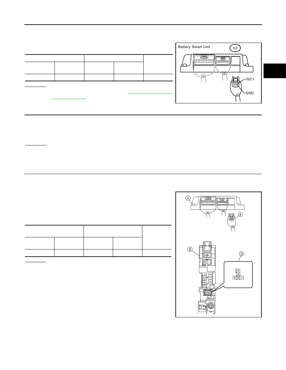
6. Disconnect the n2 battery smart unit connector.

7. Turn ignition switch ON.

8. Measure the voltage according to the value(s) in the table below.

OK or NG

OK

>> Replace battery smart unit (See 

HBB-101, "Removal

and Installation"

).

NG

>> GO TO 4.

4.

CHECK FUSE (NO. 68)

1. Remove the 10A fuse (No. 68) from the high voltage fuse and fusible link box.

2. Measure the resistance of the fuse.

OK or NG

OK

>> GO TO 5.

NG

>> Replace fuse.

5.

CHECK HARNESS AND CONNECTOR (BATTERY SMART UNIT - HIGH VOLTAGE FUSE AND FUSIBLE

LINK BOX)

CAUTION:

Be sure to wear insulated gloves.

1. Install the 10A fuse to the high voltage fuse and fusible link box.

2. Remove the IGCT relay (3) from the high voltage fuse and fus-

ible link box (2).

3. Disconnect connector n2 (4) from the battery smart unit (1).

4. Measure the resistance according to the value(s) in the table

below.

OK or NG

OK

>> Check and repair power source circuit.

NG

>> Repair or replace harness or connector.

Battery smart unit

Battery smart unit

Voltage

Harness

connector

Terminal

Harness

connector

Terminal

n2

1 (IGC1)

n2

5 (GND)

8.6 V or more

JMCIA0191GB

Resistance

: Below 1

Battery smart unit

high voltage fuse and fusible 

link box

Resistance

Harness

connector

Terminal

Harness

connector

Terminal

n2

1 (IGC1)

V-1

5 (IGCT relay)

Below 1 

ALCIA0107ZZ

HBC-198

< COMPONENT DIAGNOSIS >

P0A2B-248, P0A2B-250

P0A2B-248, P0A2B-250

Description

INFOID:0000000004211873

The resistance of the thermistor built into the motor temperature sensor changes in accordance with changes

in MG2 temperature. The lower the MG2 temperature, the more the thermistor resistance. Conversely, the

more the temperature, the lower the resistance.

DTC Logic

INFOID:0000000004211874

DTC DETECTION LOGIC

Diagnosis Procedure

INFOID:0000000004211875

1.

PRECONDITIONING

• Before inspecting the high-voltage system or disconnecting the low voltage connector of the inverter with

converter assembly, take safety precautions such as wearing insulated gloves and removing the service

plug grip to prevent electrical shocks. After removing the service plug grip, put it in your pocket to prevent

other technicians from accidentally reconnecting it while you are working on the high-voltage system.

• After disconnecting the service plug grip, wait for at least 10 minutes before touching any of the high-voltage

connectors or terminals.

• Waiting for at least 10 minutes is required to discharge the high-voltage capacitor inside the inverter with

converter assembly.

>> GO TO 2.

2.

CHECK CONNECTOR CONNECTION CONDITION (MOTOR TEMPERATURE SENSOR CONNECTOR)

Check the connection of the motor temperature sensor connector.

OK or NG

OK

>> GO TO 3.

>> Connect securely.

3.

REPLACE HYBRID TRANSAXLE

Refer to 

TM-36, "Removal and Installation"

.

>> COMPLETED

JMCIA0097GB

DTC No.

INF Code

Trouble diagnosis name

DTC detecting condition

Possible cause

P0A2B

248

Drive Motor ”A” Temperature 
Sensor Circuit Range / Perfor-
mance

Motor temperature sensor mal-
function

Hybrid transaxle (Motor temperature 
sensor)

250

Motor temperature sensor per-
formance problem

• The connectors are connected securely and there are no contact problems.
• Dirt or foreign objects have not entered the connection, or there is no evidence 

of contamination. 

P0A2C-247, P0A2D-249

HBC-199

< COMPONENT DIAGNOSIS >

D

E

F

G

H

I

J

K

L

M

A

B

HBC

N

O

P

P0A2C-247, P0A2D-249

Description

INFOID:0000000004211876

The resistance of the thermistor built into the motor temperature sensor changes in accordance with changes

in MG2 temperature. The lower the MG2 temperature, the more the thermistor resistance. Conversely, the

more the temperature, the lower the resistance.

DTC Logic

INFOID:0000000004211877

DTC DETECTION LOGIC

Diagnosis Procedure

INFOID:0000000004211878

1.

PRECONDITIONING

• Before inspecting the high-voltage system or disconnecting the low voltage connector of the inverter with

converter assembly, take safety precautions such as wearing insulated gloves and removing the service

plug grip to prevent electrical shocks. After removing the service plug grip, put it in your pocket to prevent

other technicians from accidentally reconnecting it while you are working on the high-voltage system.

• After disconnecting the service plug grip, wait for at least 10 minutes before touching any of the high-voltage

connectors or terminals.

• Waiting for at least 10 minutes is required to discharge the high-voltage capacitor inside the inverter with

converter assembly.

>> GO TO 2.

2.

CHECK CONNECTOR CONNECTION CONDITION (HYBRID VEHICLE CONTROL ECU CONNECTOR)

See 

HBC-109, "Diagnosis Procedure"

.

OK or NG

OK

>> GO TO 3.

NG

>> Connect securely.

3.

CHECK CONNECTOR CONNECTION CONDITION (MOTOR TEMPERATURE SENSOR CONNECTOR)

Check the connections of the motor temperature sensor connectors.

JMCIA0097GB

DTC No.

INF Code

Trouble diagnosis name

DTC detecting condition

Possible cause

P0A2C

247

Drive Motor “A” Temperature 
Sensor Circuit Low

GND short in motor temperature 
sensor circuit

• Wire harness or connector
• Hybrid vehicle control ECU
• Hybrid transaxle (Motor temperature 

sensor)

P0A2D

249

Drive Motor “A” Temperature 
Sensor Circuit High

Open or +B short in motor tem-
perature sensor circuit

• Wire harness or connector
• Hybrid vehicle control ECU
• Hybrid transaxle (Motor temperature 

sensor)

• The connectors are connected securely and there are no contact problems.
• Dirt or foreign objects have not entered the connection, or there is no evidence 

of contamination. 

HBC-200

< COMPONENT DIAGNOSIS >

P0A2C-247, P0A2D-249

OK or NG

OK

>> GO TO 4.

NG

>> Connect securely.

4.

READ VALUE OF DATA MONITOR (MOTOR1 TEMP)

1. Turn ignition switch ON.

2. Select “MG1 MOTOR TEMP” in DATA MONITOR mode with CONSULT-III.

3. Read the indication.

A or B or C

A

>> GO  TO  5.

B

>> GO  TO  7.

C

>> Check for intermittent incident (See 

GI-42, "Intermittent Incident"

).

5.

READ VALUE OF DATA MONITOR (MG1 MOTOR TEMP)

1. Disconnect the motor temperature sensor harness connector F60.

2. Connect terminals 7 and 9 of the motor temperature sensor vehicle side connector.

3. Turn ignition switch ON.

4. Select “MG1 MOTOR TEMP” in DATA MONITOR mode with CONSULT-III.

5. Read the indication.

OK or NG

OK

>> Replace hybrid transaxle (See 

TM-36, "Removal and Installation"

).

NG

>> GO TO 6.

6.

CHECK HARNESS AND CONNECTOR (HYBRID VEHICLE CONTROL ECU - MOTOR TEMPERATURE

SENSOR)
1. Disconnect the hybrid vehicle control ECU harness connector E65.

2. Turn ignition switch ON.

3. Measure the voltage according to the value(s) in the table below.

NOTE:

Turn ignition switch ON with the hybrid vehicle control ECU connectors disconnected causes other DTCs

to be stored. Clear the DTCs after performing this inspection.

4. Turn ignition switch OFF.

5. Disconnect the motor temperature sensor harness connector F69.

6. Measure the resistance according to the value(s) in the table below.

Check for open

A

B

C

-50

°C (-58°F)

205

°C (401°F) or more

Same as actual temperature

Displayed temperature

: 205

°C (401°F) or more

Hybrid vehicle control ECU

Ground

Voltage

Harness

connector

Terminal

E65

16 (MMT)

Ground

Below 1 V

15 (MMTG)

Hybrid vehicle control ECU

Motor temperature sensor

Resistance

Harness

connector

Terminal

Harness

connector

Terminal

E65

16 (MMT)

F69

7 (MMT)

Below 1 

15 (MMTG)

9 (MMTG)


Content   ..  610  611  612  613   ..