Nissan Altima HL32 Hybrid. Manual - part 514
U0424 ELECTRIC COMPRESSOR
HAC-77
< COMPONENT DIAGNOSIS >
[AUTOMATIC AIR CONDITIONER]
C
D
E
F
G
H
J
K
L
M
A
B
HAC
N
O
P
8.
INSPECT MG ECU
CAUTION:
• Be sure to wear insulated gloves.
• Do not touch the high-voltage connectors or terminals for 10 minutes after the service plug grip is
removed.
1. Disconnect the MG ECU connector.
2. Measure the resistance according to the value(s) in the table below.
Is the inspection result normal?
YES
>> GO TO 9.
NO
>> Replace MG ECU.
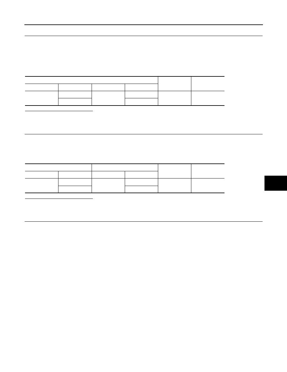
9.
MG ECU CIRCUIT
1. Disconnect the electric compressor connector.
CAUTION:
Be sure to wear insulated gloves.
2. Measure the resistance according to the value(s) in the table below.
Is the inspection result normal?
YES
>> GO TO 10.
NO
>> Repair harness or connector.
10.
INSPECT ELECTRIC COMPRESSOR
1. Reconnect the electric compressor connector.
2. Turn ignition switch ON.
3. Measure the waveform according to the following tables.
MG ECU
Condition
Resistance (
Ω)
Connector
Terminal
Connector
Terminal
F250
11
F225
1
Always
Below 1.0
12
2
Electric compressor
MG ECU
Condition
Resistance (
Ω)
Connector
Terminal
Connector
Terminal
F252
7
F250
12
Always
Below 1.0
8
11