Nissan Altima HL32 Hybrid. Manual - part 512
B2651, B2652 ELECTRIC COMPRESSOR
HAC-69
< COMPONENT DIAGNOSIS >
[AUTOMATIC AIR CONDITIONER]
C
D
E
F
G
H
J
K
L
M
A
B
HAC
N
O
P
B2651, B2652 ELECTRIC COMPRESSOR
Description
INFOID:0000000004215356
The temperature sensor of the electric compressor detects inverter temperature. If the temperature exceeds
the maximum, the electric compressor stops compressor operation, and this DTC will be output. The output
DTC of B2651 are memorized only present trouble. On B2652, compressor control may not resume unless the
ignition switch is turned OFF and waiting for 10 minutes.
DTC Logic
INFOID:0000000004215357
DTC DETECTION LOGIC
DTC CONFIRMATION PROCEDURE
1.
PRECONDITIONING
If DTC Confirmation Procedure has been previously conducted, always turn ignition switch OFF and wait at
least 10 seconds before conducting the next test.
>> GO TO 2.
2.
PERFORM DTC CONFIRMATION PROCEDURE
1. Turn ignition switch ON (READY) and wait at least 5 seconds.
2. Check DTC.
Is DTC detected?
YES
>> Go to Diagnosis Procedure.
NO
>> END.
Diagnosis Procedure
INFOID:0000000004215358
1.
CHECK CAN COMMUNICATION SYSTEM
Use the CONSULT-III to check if the CAN Communication System is functioning normally.
Is CAN DTC detected?
YES
>> Check CAN communication. Refer to
LAN-16, "Trouble Diagnosis Flow Chart"
.
NO
>> GO TO 2.
2.
PERFORM ACTIVE TEST
1. Turn ignition switch ON (READY).
2. Perform “FAN DUTY CONTROL” in “ACTIVE TEST” mode with CONSULT-III.
Does cooling fan operates smoothly?
YES
>> GO TO 3.
NO
>> Go to cooling fan system. Refer to
3.
CHECK REFRIGERANT CYCLE PRESSURE
Connect refrigerant recovery/recycling recharging equipment to the vehicle and check the refrigerant cycle
HA-21, "HFC-134a (R-134a) Service Procedure"
Is the inspection result normal?
YES
>> GO TO 4.
NO
>> Recharge refrigerant after repair or replace the parts according to the inspection results.
4.
CHECK DTC
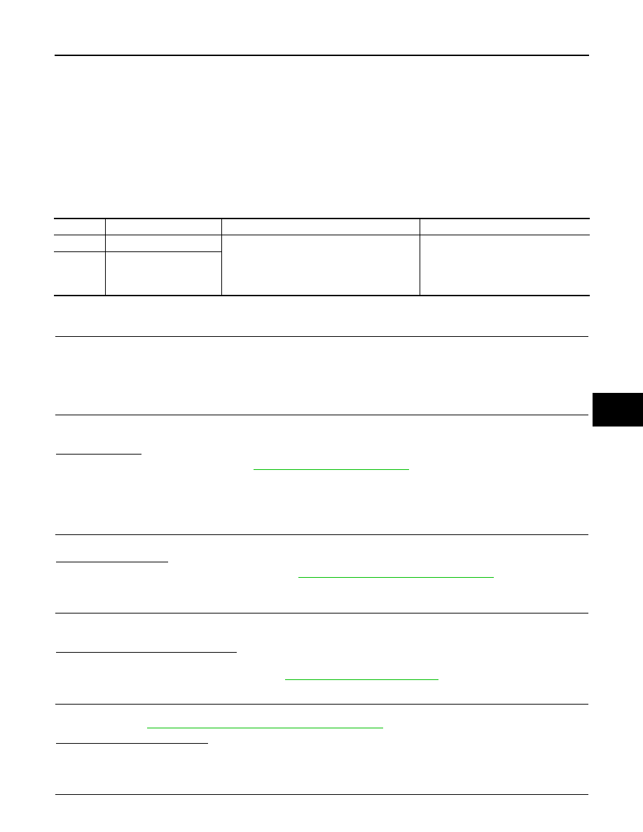
DTC No.
Trouble Diagnosis Name
DTC Detecting Condition
Possible Cause
B2651
INV OVERHEAT L
• After READY and A/C ON
• Temperature in the inverter is outside the
specified range (temperature is too high), or
there is an open or short to ground in the tem-
perature sensor circuit.
• Cooling fan system
• Refrigerant volume
• Electric compressor
• CAN communication system
B2652
INV OVERHEAT S