Nissan Altima HL32 Hybrid. Manual - part 504


  Index      Nissan     Nissan Altima HL32 Hybrid (2009 year) - Service and Repair Manual


Search            


Content   ..  502  503  504  505   ..


Nissan Altima HL32 Hybrid. Manual - part 504


B257B, B257C AMBIENT SENSOR

HAC-37

< COMPONENT DIAGNOSIS >

[AUTOMATIC AIR CONDITIONER]

C

D

E

F

G

H

J

K

L

M

A

B

HAC

N

O

P

B257B, B257C AMBIENT SENSOR

Description

INFOID:0000000004215314

COMPONENT DESCRIPTION
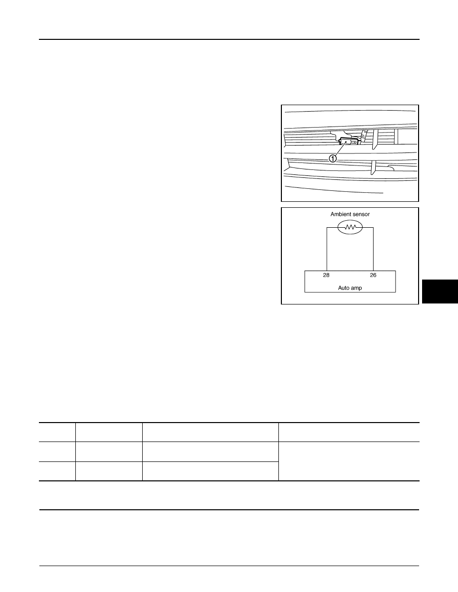
Ambient Sensor

The ambient sensor (1) is attached on the radiator core support (left

side). It detects ambient temperature and converts it into a resis-

tance value which is then input into the auto amp.

Ambient Sensor Circuit

AMBIENT TEMPERATURE INPUT PROCESS

The auto amp. includes a processing circuit for the ambient sensor input. However, when the temperature

detected by the ambient sensor increases quickly, the processing circuit retards the auto amp. function. It only

allows the auto amp. to recognize an ambient temperature increase of 0.33

°C (0.6°F) per 100 seconds.

As an example, consider stopping for a few minutes after high speed driving. Although the actual ambient tem-

perature has not changed, the temperature detected by the ambient sensor will increase. This is because the

heat from the engine compartment can radiate to the front bumper area, location of the ambient sensor.

DTC Logic

INFOID:0000000004215315

DTC DETECTION LOGIC

DTC CONFIRMATION PROCEDURE

1.

PRECONDITIONING

If DTC Confirmation Procedure has been previously conducted, always turn ignition switch OFF and wait at

least 10 seconds before conducting the next test.

>> GO TO 2.

2.

PERFORM DTC CONFIRMATION PROCEDURE

JPIIA0041ZZ

JPIIA0057GB

DTC No.

Trouble Diagnosis 

Name

DTC Detecting Condition

Possible Cause

B257B

AMB TEMP SEN
SHORT

Short in ambient sensor circuit.

• Ambient sensor 
• Auto amp.
• Harness or connectors

(The sensor circuit is open or shorted.)

B257C

AMB TEMP SEN
OPEN

Open in ambient sensor circuit.

HAC-38

< COMPONENT DIAGNOSIS >

[AUTOMATIC AIR CONDITIONER]

B257B, B257C AMBIENT SENSOR

1. Turn ignition switch ON and wait at least 5 seconds.

2. Check DTC.
Is DTC detected?

YES

>> Go to Diagnosis Procedure. 

HAC-38, "Diagnosis Procedure"

.

NO

>> END.

Diagnosis Procedure

INFOID:0000000004215316

1.

CHECK VOLTAGE BETWEEN AMBIENT SENSOR AND GROUND

1. Disconnect ambient sensor connector.

2. Turn ignition switch ON.

3. Check voltage between ambient sensor harness connector E211 terminal 1 and ground.

Is the inspection result normal?

YES

>> GO TO 2.

NO

>> GO TO 4.

2.

CHECK CIRCUIT CONTINUITY BETWEEN AMBIENT SENSOR AND AUTO AMP. 

1. Turn ignition switch OFF.

2. Disconnect auto amp. connector.

3. Check continuity between ambient sensor harness connector E211 terminal 2 and auto amp. harness

connector M37 terminal 26.

Is the inspection result normal?

YES

>> GO TO 3.

NO

>> Repair harness or connector.

3.

CHECK AMBIENT SENSOR

Refer to 

HAC-39, "Component Inspection"

.

Is the inspection result normal?

YES

>> Replace auto amp. Refer to 

VTL-8, "Removal and Installation"

.

NO

>> Replace ambient sensor. Refer to 

VTL-11, "Removal and Installation"

.

4.

CHECK CIRCUIT CONTINUITY BETWEEN AMBIENT SENSOR AND AUTO AMP.

1. Turn ignition switch OFF.

2. Disconnect auto amp. connector.

3. Check continuity between ambient sensor harness connector E211 terminal 1 and auto amp. harness

connector M37 terminal 28.

4. Check continuity between ambient sensor harness connector E211 terminal 1 and ground.

(+)

(

−)

Voltage

Ambient sensor

Connector

Terminal

E211

1

Ground

Approx. 5

Ambient sensor

Auto amp.

Continuity

Connector

Terminal

Connector

Terminal

E211

2

M37

26

Continuity should exist

Ambient sensor

Auto amp.

Continuity

Connector

Terminal

Connector

Terminal

E211

1

M37

28

Continuity should exist

B257B, B257C AMBIENT SENSOR

HAC-39

< COMPONENT DIAGNOSIS >

[AUTOMATIC AIR CONDITIONER]

C

D

E

F

G

H

J

K

L

M

A

B

HAC

N

O

P

Is the inspection result normal?

YES

>> Replace auto amp. Refer to 

VTL-8, "Removal and Installation"

.

NO

>> Repair harness or connector.

Component Inspection

INFOID:0000000004215317

After disconnecting ambient sensor (1) connector E211, measure

resistance between terminals 1 and 2 at sensor side. Refer to table

below.

If NG, replace ambient sensor. Refer to 

VTL-11, "Removal and

Installation"

.

Ambient sensor

Continuity

Connector

Terminal

E211

1

Ground

Continuity should not exist

Temperature 

°C (°F)

Resistance k

−15 (5)

12.73

−10 (14)

9.92

−5 (23)

7.80

0 (32)

6.19

5 (41)

4.95

10 (50)

3.99

15 (59)

3.24

20 (68)

2.65

25 (77)

2.19

30 (86)

1.81

35 (95)

1.51

40 (104)

1.27

45 (113)

1.07

JPIIA0042ZZ

HAC-40

< COMPONENT DIAGNOSIS >

[AUTOMATIC AIR CONDITIONER]

B2581, B2582 INTAKE SENSOR

B2581, B2582 INTAKE SENSOR

Description

INFOID:0000000004215318

Intake Sensor

The intake sensor (1) is located on the heater & cooling unit assem-

bly. It converts temperature of air after it passes through the evapo-

rator (2) into a resistance value which is then input to the auto amp.

Intake Sensor Circuit

DTC Logic

INFOID:0000000004215319

DTC DETECTION LOGIC

DTC CONFIRMATION PROCEDURE

1.

PRECONDITIONING

If DTC Confirmation Procedure has been previously conducted, always turn ignition switch OFF and wait at

least 10 seconds before conducting the next test.

>> GO TO 2.

2.

PERFORM DTC CONFIRMATION PROCEDURE

1. Turn ignition switch ON and wait at least 5 seconds.

2. Check DTC.
Is DTC detected?

YES

>> Go to Diagnosis Procedure. 

HAC-40, "Diagnosis Procedure"

.

NO

>> END.

Diagnosis Procedure

INFOID:0000000004215320

1.

CHECK VOLTAGE BETWEEN INTAKE SENSOR AND GROUND

JPIIA0050ZZ

JPIIA0051GB

DTC No.

Trouble Diagnosis 

Name

DTC Detecting Condition

Possible Cause

B2581

EVAP TEMP SEN
SHORT

Short in intake sensor circuit.

• Intake sensor 
• Auto amp.
• Harness or connectors

(The sensor circuit is open or shorted.)

B2582

EVAP TEMP SEN
OPEN

Open in intake sensor circuit.


Content   ..  502  503  504  505   ..