Nissan Altima HL32 Hybrid. Manual - part 462
 

  Index      Nissan     Nissan Altima HL32 Hybrid (2009 year) - Service and Repair Manual


Search            


Content   ..  460  461  462  463   ..


Nissan Altima HL32 Hybrid. Manual - part 462


TRANSVERSE LINK

FSU-11

< ON-VEHICLE REPAIR >

C

D

F

G

H

I

J

K

L

M

A

B

FSU

N

O

P

TRANSVERSE LINK

Removal and Installation

INFOID:0000000004523245

REMOVAL

1. Remove wheel and tire using power tool. Refer to 

WT-62, "Adjustment"

.

2. Remove steering knuckle from transverse link. Refer to 

FSU-13, "Exploded View"

.

3. Remove mounting nuts and washers on lower portion of stabilizer connecting rod.
4. Slightly loosen transverse link mounting bolts.
5. Remove transverse link mounting bolts and nuts, and remove transverse link from suspension member.

INSPECTION AFTER REMOVAL

Visual Inspection

Check transverse link and bushing for deformation, cracks, and other damage. Replace the entire transverse

link assembly if cracks, deformation or any other damage is found.

Ball Joint Inspection

CAUTION:

Before measurement, move the ball joint at least ten times by hand to check for smooth movement.

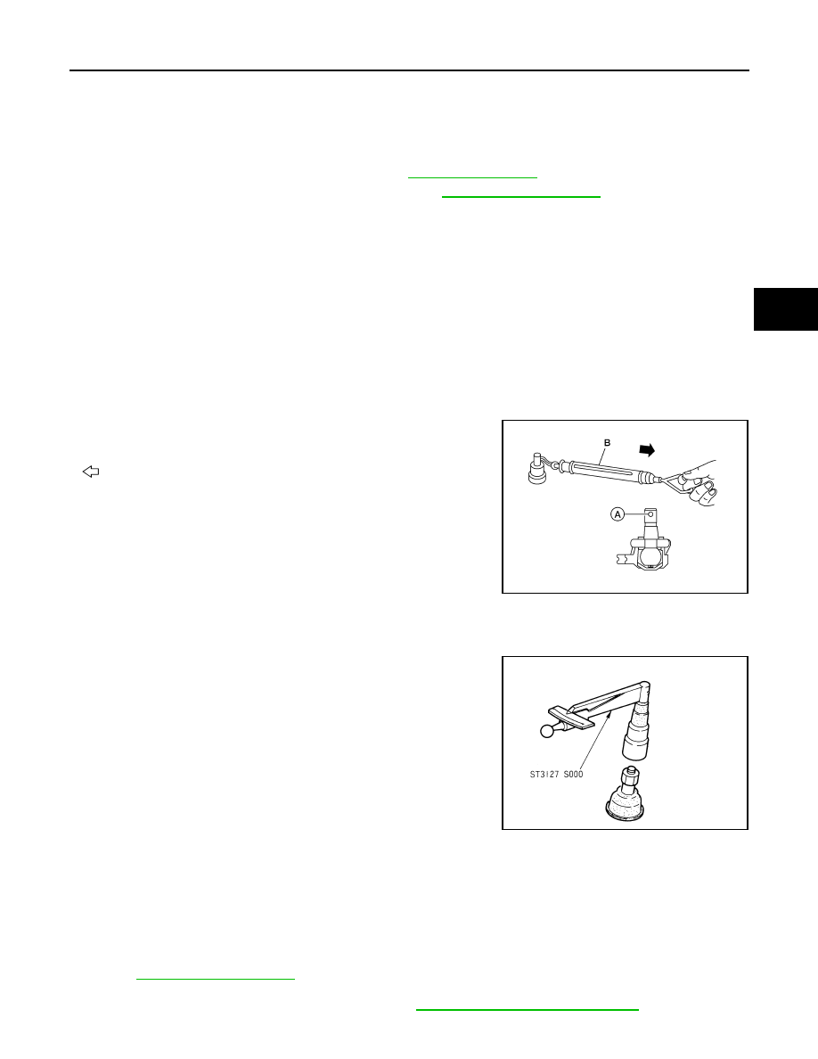
Swing Torque Inspection

• Hook Tool (B) at cotter pin mounting hole (A). Confirm Tool (B)

measurement value is within specifications when ball stud begins

moving.

: Front

• If the value is outside the standard, replace transverse link.

Rotating Torque Inspection

• Attach mounting nut to ball stud. Check that rotating torque is

within specifications using Tool.

• If the value is outside the standard, replace transverse link.

Axial End Play Inspection

• Move tip of ball joint in axial direction to check for looseness.

• If any looseness is noted, replace transverse link.

INSTALLATION

Installation is in the reverse order of removal.

• Refer to 

FSU-13, "Exploded View"

 for tightening torque specifications.

• Tighten transverse link mounting bolts with vehicle unladen and all four tire on flat, level ground.

• After installation, check the wheel alignment. Refer to 

FSU-6, "Inspection and Adjustment"

.

Tool number

: — (J-44372)

Swing torque

: 0.50 - 3.4 N·m (0.06 - 0.34 kg-m, 
5 - 30 in-lb)

Measurement on Tool

: 7.94 - 53.97 N (0.81 - 5.50 kg, 
1.79 - 12.2 lb)

AWGIA0066ZZ

Tool number

: ST3127S000 (J-25765-A)

Rotating torque

: 0.50 - 3.4 N·m (0.06 - 0.34 kg-m, 
5 - 30 in-lb)

FAC1021D

Axial end play : 0.1 mm (0.004 in) or less

FSU-12

< ON-VEHICLE REPAIR >

FRONT STABILIZER

FRONT STABILIZER

Removal and Installation

INFOID:0000000004523246

REMOVAL

1. Remove the wheel and tire using power tool. Refer to 

WT-62, "Adjustment"

.

2. Remove the stabilizer connecting rod nuts from the strut.

3. Remove stabilizer clamp bolts.
4. Remove stabilizer bar.

INSPECTION AFTER REMOVAL

Check stabilizer bar, connecting rod, bushing and clamp for deformation, cracks and damage, and replace as

necessary.

INSTALLATION

Installation is in the reverse order of removal. Refer to 

FSU-13, "Exploded View"

 for tightening torque specifi-

cations.

• When installing stabilizer bar, make sure that the clamps are facing

in the direction as shown. 

• Make sure the cut surface of the stabilizer bushing faces the rear

of the vehicle.

•  Stabilizer bar uses pillow ball type connecting rod. Position ball

joint with case on pillow ball head parallel to stabilizer as shown.

SFA796B

WEIA0073E

SFA449BB

FRONT SUSPENSION ASSEMBLY

FSU-13

< REMOVAL AND INSTALLATION >

C

D

F

G

H

I

J

K

L

M

A

B

FSU

N

O

P

REMOVAL AND INSTALLATION

FRONT SUSPENSION ASSEMBLY

Exploded View

INFOID:0000000004523249

AWEIA0001GB

FSU-14

< REMOVAL AND INSTALLATION >

FRONT SUSPENSION ASSEMBLY

Removal and Installation

INFOID:0000000004523250

REMOVAL

The engine and transaxle are removed as an assembly mounted to the front suspension member. Refer to

EM-71, "Removal and Installation"

Once removed as an assembly, remove the front suspension member

from the engine and transaxle assembly.

INSTALLATION

Installation is in the reverse order of removal.

• Refer to 

FSU-13, "Exploded View"

 for tightening torque specifications.

• After installation, perform final tightening of each part under unladen conditions with tires on ground.

• Check wheel alignment. Refer to 

FSU-6, "Inspection and Adjustment"

.

1.

Strut tower bar

2.

Stabilizer bar

3.

Stabilizer clamp

4.

Stabilizer bushing

5.

Connecting rod

6.

Engine mount bracket

7.

Member pin stay

8.

Transverse link

9.

Steering stop plate

10. Steering stop

11. Steering knuckle

12. Front suspension member

13. Strut

14. Lower rubber seat

15. Coil spring

16. Upper rubber seat

17. Dust cover

18. Strut mount insulator


Content   ..  460  461  462  463   ..