Nissan Altima HL32 Hybrid. Manual - part 390


  Index      Nissan     Nissan Altima HL32 Hybrid (2009 year) - Service and Repair Manual


Search            


Content   ..  388  389  390  391   ..


Nissan Altima HL32 Hybrid. Manual - part 390


EM-74

< REMOVAL AND INSTALLATION >

[QR25DE]

ENGINE ASSEMBLY

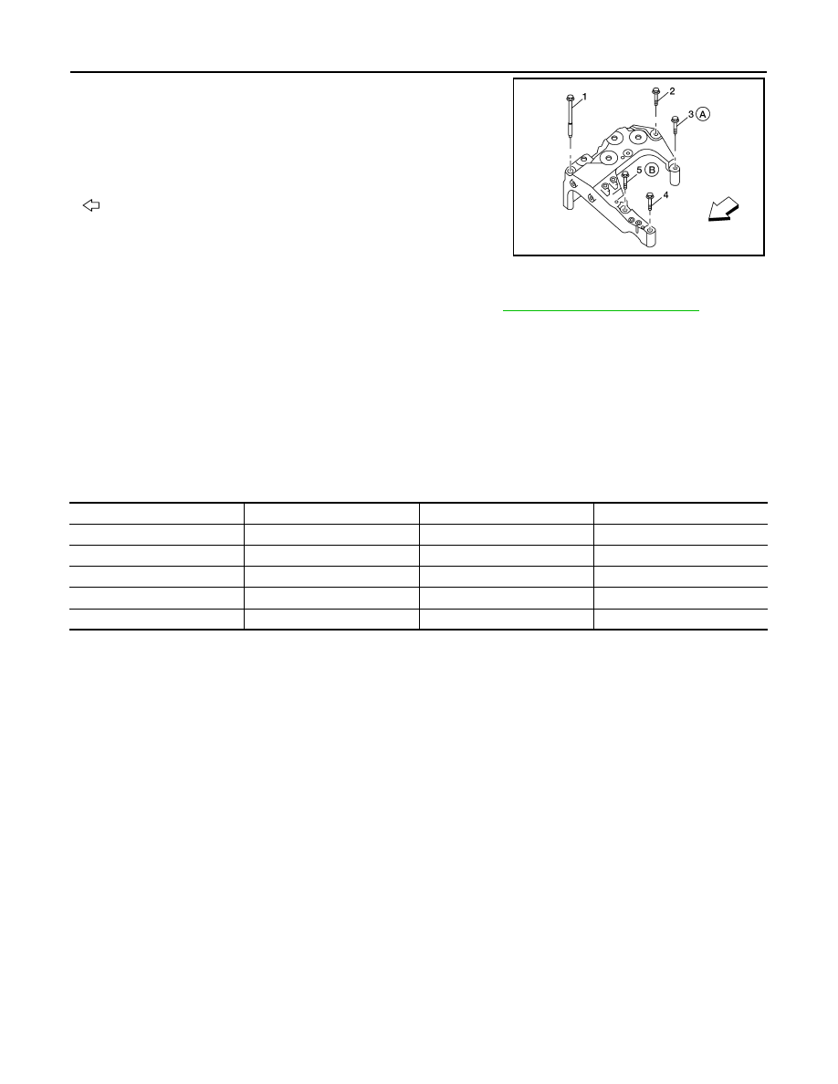
• Install the RH engine mounting bracket bolts in the following steps:

- First install bolts (A) and (B) loosely.

- Install and tighten the five RH engine mounting bracket bolts to

specification in the order as shown.

-

: Front

INSPECTION AFTER INSTALLATION

• Before starting the hybrid system, check oil/fluid levels including hybrid system coolant and hybrid system

oil. If less than required quantity, fill to the specified level. Refer to 

MA-10, "Fluids and Lubricants"

.

• Use procedure below to check for fuel leakage.

- Turn ignition switch ON (with hybrid system stopped). With fuel pressure applied to fuel piping, check for fuel

leakage at connection points.

- Start the hybrid system. With engine speed increased, check again for fuel leakage at connection points.

- Run hybrid system to check for unusual noise and vibration.

- Warm up hybrid system thoroughly to make sure there is no leakage of fuel, exhaust gas, or any oils/fluids

including hybrid system oil and hybrid system coolant.

• Bleed air from passages in lines and hoses, such as in cooling system.

• After cooling down hybrid system, again check oils/fluids including hybrid system oil and hybrid system cool-

ant. Refill to specified level, if necessary.

• Summary of the inspection items:

*Transaxle/CVT fluid, brake fluid, etc.

RH engine mounting bracket bolt : 48.2 N·m (4.9 kg-m, 

36 ft-lb)

ALBIA0541ZZ

Item

Before starting engine

Engine running

After engine stopped

Hybrid system coolant

Level

Leakage

Level

Hybrid system oil

Level

Leakage

Level

Other oils and fluids*

Level

Leakage

Level

Fuel

Leakage

Leakage

Leakage

Exhaust gas

Leakage

CYLINDER BLOCK

EM-75

< DISASSEMBLY AND ASSEMBLY >

[QR25DE]

C

D

E

F

G

H

I

J

K

L

M

A

EM

N

P

O

DISASSEMBLY AND ASSEMBLY

CYLINDER BLOCK

Disassembly and Assembly

INFOID:0000000004211260

AWBIA0595GB

1.

Cylinder block

2.

O-ring

3.

Crankshaft position sensor (POS)

4.

Knock sensor

5.

Lower cylinder block

6.

Lower cylinder block bolt 

7.

Snap ring

8.

Connecting rod

9.

Connecting rod bearing

10. Connecting rod bearing cap

11. Connecting rod bearing cap bolt 12. Piston

13. Oil ring

14. Second ring

15. Top ring

16. Piston pin

17. Main thrust bearing

18. Main bearing upper

19. Crankshaft

20. Main bearing lower

21. Crankshaft rear oil seal 

22. Crankshaft signal plate

23. Drive plate

24. Reinforcement plate

25. Cylinder block heater (if 

equipped) 

A.

Follow installation procedure

EM-76

< DISASSEMBLY AND ASSEMBLY >

[QR25DE]

CYLINDER BLOCK

CAUTION:

Apply new engine oil to parts marked in illustration before installation.

DISASSEMBLY

1. Remove the engine and transaxle as an assembly from the vehicle, and separate the transaxle from the

engine. Refer to 

EM-71, "Removal and Installation"

.

2. Mount the engine on a suitable engine stand.
3. Drain any remaining engine oil and coolant from the engine.
4. Remove the following components and associated parts.

• Exhaust manifold and three way catalyst assembly. Refer to 

EM-29, "Removal and Installation"

.

• Intake manifold collector. Refer to 

EM-25, "Removal and Installation"

.

• Intake manifold and fuel tube assembly. Refer to 

EM-25, "Removal and Installation"

.

• Ignition coils. Refer to 

EM-34, "Removal and Installation"

.

• Rocker cover. Refer to 

EM-38, "Removal and Installation"

.

• Front cover, timing chain, and balancer unit. Refer to 

EM-51, "Removal and Installation"

.

• Cylinder head. Refer to 

EM-62, "Removal and Installation"

.

5. Remove the knock sensor.

CAUTION:

Carefully handle the sensor and do not drop the sensor.

6. Remove crankshaft position sensor (POS).

CAUTION:

• Avoid impacts such as a dropping.

• Do not disassemble.

• Keep it away from metal particles.

• Do not place sensor close to magnetic materials.

7. Remove the drive plate. Hold the crankshaft with a stopper plate

and use a suitable tool to remove the bolts.    

CAUTION:

• Be careful not to damage the drive plate.

8. Remove the piston and connecting rod assemblies.
a. Position the crankshaft and corresponding connecting rod, to be

removed, to the bottom dead center stroke. 

b. Remove the connecting rod cap. Number the cap so it can be

assembled in the same position.

c.

Using a hammer handle or similar tool, push the piston and con-

necting rod assembly out of the top of the cylinder block. Num-

ber the piston and rod so it can be assembled in the same

position.

• Before removing the piston and connecting rod assembly,

check the connecting rod side clearance. Refer to 

EM-83,

"Inspection After Disassembly"

.

9. Remove the connecting rod bearings. If reusing, number them so they can be assembled in the same

position and direction.

CAUTION:

• When removing them, note the installation position. Keep them in the correct order.

KBIA0062E

PBIC0259E

CYLINDER BLOCK

EM-77

< DISASSEMBLY AND ASSEMBLY >

[QR25DE]

C

D

E

F

G

H

I

J

K

L

M

A

EM

N

P

O

10. Remove the piston rings from the piston. 

• Use a piston ring expander.

• Before removing the piston rings, check the piston ring side

clearance. Refer to 

EM-83, "Inspection After Disassembly"

.

CAUTION:

• When removing the piston rings, be careful not to damage

the piston.

• Be careful not to damage piston rings by expanding them

excessively, if reusing them.

11. Remove the piston from the connecting rod as follows. 
a. Using a snap ring pliers, remove the two snap rings.

b. Heat the piston to 60

° - 70°C (140° - 158°F) with a heat gun, or

equivalent.

c. Push out piston pin with a punch of an outer diameter of approx-

imately 19 mm (0.75 in).

PBIC0087E

PBIC0260E

PBIC0261E

PBIC0262E


Content   ..  388  389  390  391   ..