Nissan Altima HL32 Hybrid. Manual - part 375


  Index      Nissan     Nissan Altima HL32 Hybrid (2009 year) - Service and Repair Manual


Search            


Content   ..  373  374  375  376   ..


Nissan Altima HL32 Hybrid. Manual - part 375


EM-14

< ON-VEHICLE MAINTENANCE >

[QR25DE]

DRIVE BELTS

DRIVE BELTS

Checking Drive Belts

INFOID:0000000004211235

WARNING:

Inspect the drive belt only when the Hybrid System is off.

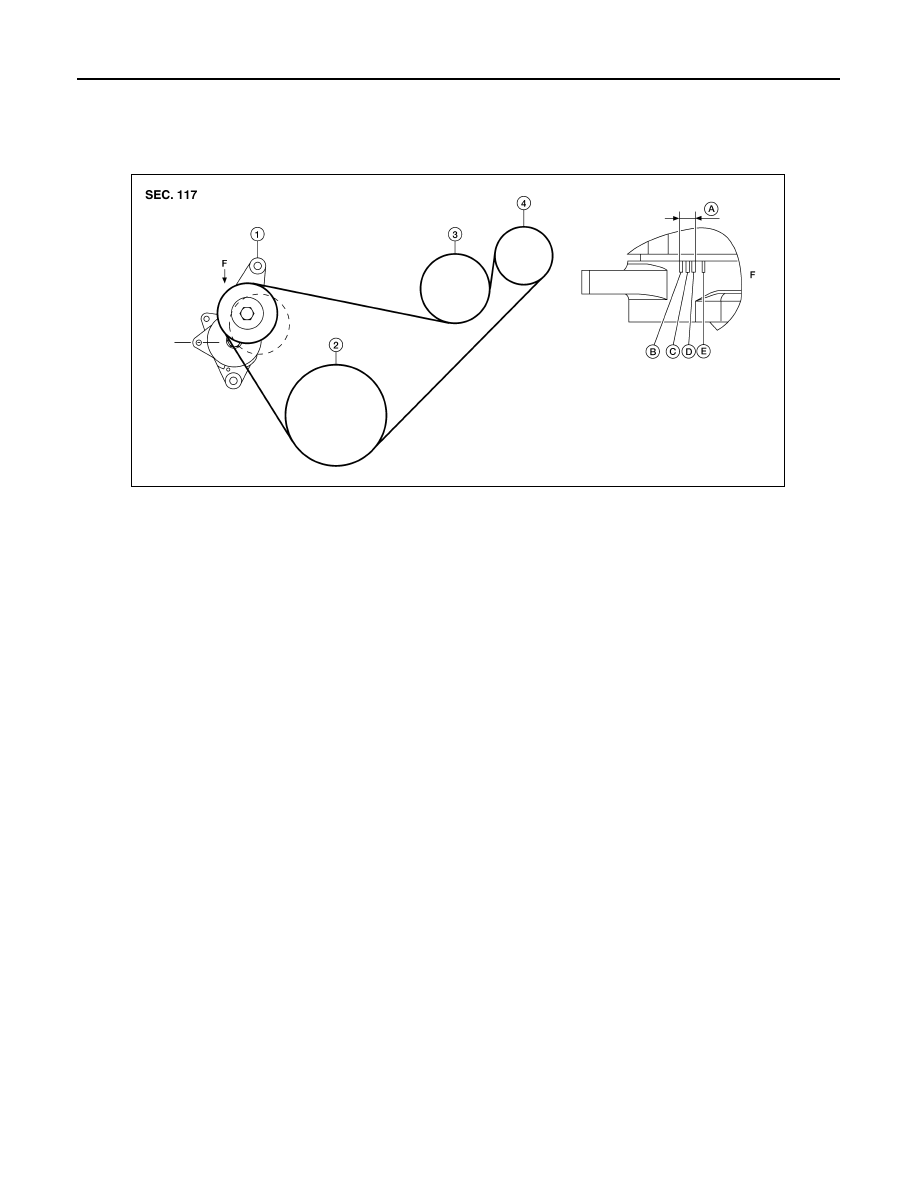
• Make sure that the stamp mark of drive belt auto-tensioner is within the usable range. 

NOTE:

• Check the drive belt auto-tensioner indicator (notch) when the engine is cold.

• When the new drive belt is installed, the range should be (A) as shown.

• Visually check entire belt for wear, damage or cracks.

• If the indicator is out of allowable use range or belt is damaged, replace the belt.

Tension Adjustment

INFOID:0000000004211236

• Belt tension is not manually adjustable, it is automatically adjusted by the drive belt auto-tensioner.

Removal and Installation of Drive Belt

INFOID:0000000004211237

REMOVAL

1. Remove the fender protector side cover (RH).
2. Securely hold the hexagonal part in pulley center of drive belt auto-tensioner, using suitable tool.

WARNING:

• Avoid placing hand in a location where pinching may occur if the holding tool accidentally

comes off.

CAUTION:

• Do not loosen the auto-tensioner pulley bolt. (Do not turn it counterclockwise) If turned counter-

clockwise, the complete auto-tensioner must be replaced as a unit, including pulley.

3. Insert a rod approximately 6 mm (0.24 in) in diameter through the rear of tensioner into retaining boss to

lock tensioner pulley.

• Leave tensioner pulley arm locked until belt is installed again.

4. Loosen auxiliary drive belt from water pump pulley in sequence, and remove it. 

INSTALLATION

1.

Drive belt auto-tensioner 

2.

Crankshaft

3.

Water pump

4.

Idler pulley

A.

Water pump belt working range B.

Minimum belt length

C.

Nominal position

D.

Maximum belt length

E.

Maximum belt length +0.8%

F.

View F

AWBIA0586ZZ

DRIVE BELTS

EM-15

< ON-VEHICLE MAINTENANCE >

[QR25DE]

C

D

E

F

G

H

I

J

K

L

M

A

EM

N

P

O

1. Hook the auxiliary drive belt onto all of the pulleys except for the water pump pulley. Hook the drive belt

onto water pump pulley last.

CAUTION:

Confirm belts are completely set on the pulleys.
2. Release tensioner, and apply tension to belt.

WARNING:

• Avoid placing hand in a location where pinching may occur if the holding tool accidentally

comes off.

CAUTION:

• Do not loosen the auto-tensioner pulley bolt. (Don't turn it counterclockwise). If turned counter-

clockwise, the complete auto-tensioner must be replaced as a unit, including pulley.

3. Turn crankshaft pulley clockwise several times to equalize tension between each pulley.
4. Confirm tensions of belt at indicator is within the allowable use range. Refer to 

EM-14, "Checking Drive

Belts"

.

Removal and Installation of Drive Belt Auto-tensioner

INFOID:0000000004211238

CAUTION:

The complete drive belt auto-tensioner must be replaced as a unit, including the pulley, do not disas-

semble.

REMOVAL

1. Disconnect the 12-volt battery negative terminal.
2. Remove the front RH wheel and tire assembly. Refer to 

WT-62, "Adjustment"

.

3. Remove the fender protector side cover (RH).
4. Remove the engine cover.
5. Remove the drive belt. Refer to 

EM-14, "Removal and Installation of Drive Belt"

• Insert a rod approximately 6 mm (0.24 in) in diameter through the rear of the tensioner into the retaining

boss to lock the tensioner pulley.

6. Remove the brake ECU and position aside. Refer to 

BRC-198, "Removal and Installation"

.

7. Remove the RH engine mounting bracket. Refer to 

EM-71, "Removal and Installation"

.

8. Remove the drive belt auto-tensioner, with power tool.

CAUTION:

• Do not loosen the auto-tensioner pulley bolt. (Do not turn it counterclockwise). If turned counter-

clockwise, the complete auto-tensioner must be replaced as a unit, including pulley.

1.

Nut bracket

2. Drive belt auto-tensioner

A.

Cylinder head

B. Cylinder block

Z. Back view

AWBIA0587ZZ

EM-16

< ON-VEHICLE MAINTENANCE >

[QR25DE]

DRIVE BELTS

• Do not swap the pulley between the new and old auto-tensioner units

INSTALLATION

Installation is in the reverse order of removal.

CAUTION:

If there is damage greater than peeled paint, replace drive belt auto-tensioner units

Removal and Installation of Idler Pulley

INFOID:0000000004485931

REMOVAL

1. Remove the front RH wheel and tire assembly. Refer to 

WT-62, "Adjustment"

.

2. Remove the drive belt. Refer to 

EM-14, "Removal and Installation of Drive Belt"

.

3. Remove the front air duct. Refer to 

EM-24, "Removal and Installation"

.

4. Disconnect the engine compartment ground harness and remove the engine compartment ground har-

ness bracket.

5. Remove the idler pulley bracket bolts in the reverse order as

shown. Then remove the idler pulley assembly.

1.

Idler pulley bracket

2.

Idler pulley

A.

Refer to Installation

ALBIA0539GB

ALBIA0540ZZ

DRIVE BELTS

EM-17

< ON-VEHICLE MAINTENANCE >

[QR25DE]

C

D

E

F

G

H

I

J

K

L

M

A

EM

N

P

O

INSTALLATION

Installation is in the reverse order of removal.

CAUTION:

Tighten the idler pulley bracket bolts using the following steps:

Step 1: Temporarily tighten bolt 1 to hold the idler pulley assem-

bly in place.

Step 2: Tighten bolt 2 to specification.

Step 3: Tighten bolt 3 to specification.

Step 4: Tighten bolt 1 to specification.

Idler pulley bracket bolts : 55.0 N·m (5.6 kg-m, 41 ft-lb)

ALBIA0540ZZ


Content   ..  373  374  375  376   ..