Nissan Altima HL32 Hybrid. Manual - part 369


  Index      Nissan     Nissan Altima HL32 Hybrid (2009 year) - Service and Repair Manual


Search            


Content   ..  367  368  369  370   ..


Nissan Altima HL32 Hybrid. Manual - part 369


EC-460

< PRECAUTION >

[QR25DE]

PRECAUTIONS

General Precautions

INFOID:0000000004211671

• Always use a 12 volt battery as power source.

• Do not attempt to disconnect battery cables while engine is

running.

• Before connecting or disconnecting the ECM harness con-

nector, turn ignition switch OFF and disconnect negative bat-

tery cable. Failure to do so may damage the ECM because

battery voltage is applied to ECM even if ignition switch is

turned OFF.

• Before removing parts, turn ignition switch OFF and then dis-

connect battery ground cable.

• Do not disassemble ECM.

• If a battery cable is disconnected, the memory will return to

the ECM value.

The ECM will now start to self-control at its initial value.

Engine operation can vary slightly when the terminal is dis-

connected. However, this is not an indication of a malfunc-

tion. Do not replace parts because of a slight variation.

• If the battery is disconnected, the following emission-related

diagnostic information will be lost within 24 hours.

Diagnostic trouble codes

1st trip diagnostic trouble codes

Freeze frame data

1st trip freeze frame data

System readiness test (SRT) codes

Test values

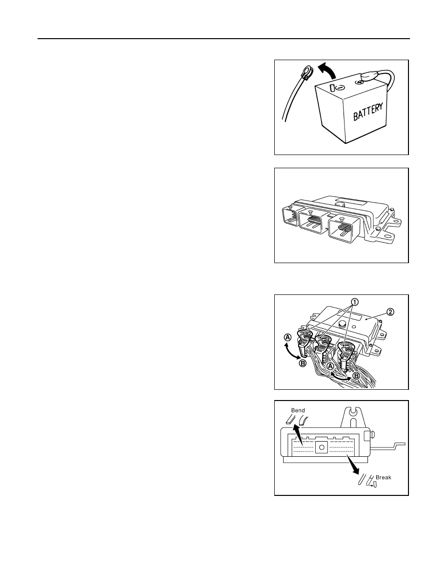
• When connecting ECM harness connector (1), fasten (B) it

securely with a lever as far as it will go as shown in the figure.

• When connecting or disconnecting pin connectors into or

from ECM, take care not to damage pin terminals (bend or

break).

Make sure that there are not any bends or breaks on ECM pin

terminal, when connecting pin connectors.

• Securely connect ECM harness connectors.

A poor connection can cause an extremely high (surge) volt-

age to develop in coil and condenser, thus resulting in dam-

age to ICs.

• Keep engine control system harness at least 10 cm (4 in) away

from adjacent harness, to prevent engine control system mal-

functions due to receiving external noise, degraded operation

of ICs, etc.

• Keep engine control system parts and harness dry.

SEF289H

2.

ECM

A.

Loosen

PBIA9222J

PBIB2947E

PBIB0090E

PRECAUTIONS

EC-461

< PRECAUTION >

[QR25DE]

C

D

E

F

G

H

I

J

K

L

M

A

EC

N

P

O

• Before replacing ECM, perform ECM Terminals and Reference

Value inspection and make sure ECM functions properly.

Refer to 

EC-405, "Reference Value"

.

• Handle mass air flow sensor carefully to avoid damage.

• Do not clean mass air flow sensor with any type of detergent.

• Do not disassemble electric throttle control actuator.

• Even a slight leak in the air intake system can cause serious

incidents.

• Do not shock or jar the camshaft position sensor (PHASE),

crankshaft position sensor (POS).

• After performing each TROUBLE DIAGNOSIS, perform DTC

CONFIRMATION PROCEDURE or Component Function

Check. The DTC should not be displayed in the DTC Confir-

mation Procedure if the repair is completed. The Component

Function Check should be a good result if the repair is com-

pleted.

• When measuring ECM signals with a circuit tester, never allow

the two tester probes to contact.

Accidental contact of probes will cause a short circuit and

damage the ECM power transistor.

• Do not use ECM ground terminals when measuring input/out-

put voltage. Doing so may result in damage to the ECM’s tran-

sistor. Use a ground other than ECM terminals, such as the

ground.

• Do not operate fuel pump when there is no fuel in lines.

• Tighten fuel hose clamps to the specified torque.

MEF040D

SEF217U

SEF348N

EC-462

< PRECAUTION >

[QR25DE]

PRECAUTIONS

• Do not depress accelerator pedal when starting.

• Immediately after starting, do not rev up engine unnecessar-

ily.

• Do not rev up engine just prior to shutdown.

• When installing C.B. ham radio or a mobile phone, be sure to

observe the following as it may adversely affect electronic

control systems depending on installation location.

Keep the antenna as far as possible from the electronic con-

trol units.

Keep the antenna feeder line more than 20 cm (8 in) away

from the harness of electronic controls.

Do not let them run parallel for a long distance.

Adjust the antenna and feeder line so that the standing-wave

ratio can be kept smaller.

Be sure to ground the radio to vehicle body.

SEF709Y

SEF708Y

PREPARATION

EC-463

< PREPARATION >

[QR25DE]

C

D

E

F

G

H

I

J

K

L

M

A

EC

N

P

O

PREPARATION

PREPARATION

Special Service Tools

INFOID:0000000004211672

NOTE:

The actual shapes of Kent-Moore tools may differ from those of special service tools illustrated here.

Commercial Service Tools

INFOID:0000000004211673

Tool number
(Kent-Moore No.)
Tool name

Description

(J-44321)
Fuel pressure gauge 
kit

Checking fuel pressure

LEC642

Tool name
(Kent-Moore No.)

Description

Leak detector 
i.e.: (J-41416)

Locating the EVAP leak

EVAP service port 
adapter
i.e.: (J-41413-OBD)

Applying positive pressure through EVAP service 
port

Fuel filler cap adapter
i.e.: (MLR-8382)

Checking fuel tank vacuum relief valve opening 
pressure

Socket wrench

Removing and installing engine coolant tempera-
ture sensor

S-NT703

S-NT704

S-NT815

S-NT705


Content   ..  367  368  369  370   ..