Nissan Altima HL32 Hybrid. Manual - part 368
EC-456
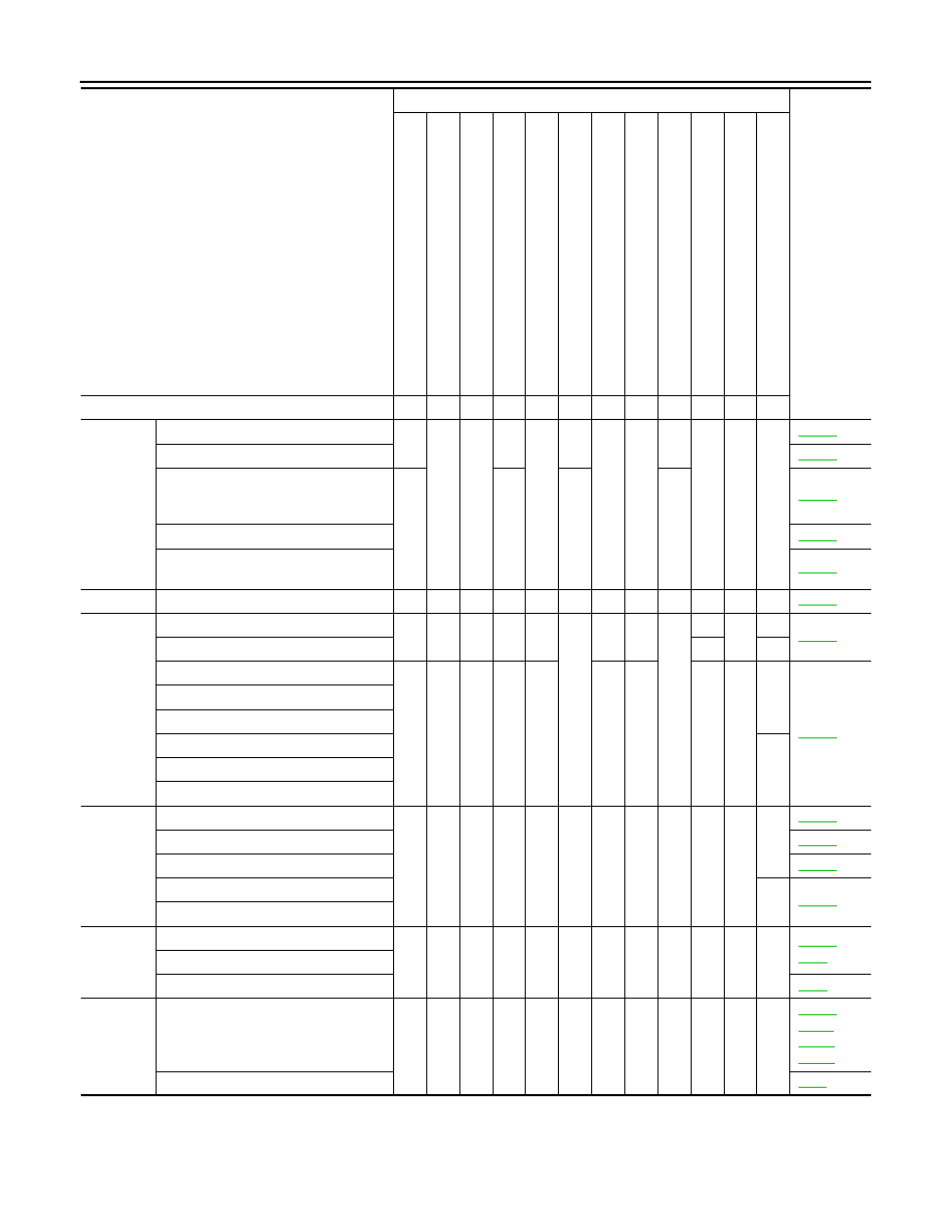
< SYMPTOM DIAGNOSIS >
[QR25DE]
ENGINE CONTROL SYSTEM SYMPTOMS
Air
Air duct
5
5
5
5
5
5
Air cleaner
Air leakage from air duct
(Mass air flow sensor — electric throt-
tle control actuator)
5
5
5
5
Electric throttle control actuator
Air leakage from intake manifold/Col-
lector/Gasket
Cranking
Signal plate
6
1
Engine
Cylinder head
5
5
5
5
5
5
5
5
Cylinder head gasket
4
3
Cylinder block
6
6
6
6
6
6
6
6
4
Piston
Piston ring
Connecting rod
Bearing
Crankshaft
Valve
mecha-
nism
Timing chain
5
5
5
5
5
5
5
5
Camshaft
Intake valve timing control
Intake valve
3
Exhaust valve
Exhaust
Exhaust manifold/Tube/Muffler/Gasket
5
5
5
5
5
5
5
5
,
Three way catalyst
HC adsorption catalyst
Lubrica-
tion
Oil pan/Oil strainer/Oil pump/Oil filter/
Oil gallery/Oil cooler
5
5
5
5
5
5
5
5
,
Oil level (Low)/Filthy oil
SYMPTOM
Reference
page
HARD/NO S
TA
R
T/RES
TA
R
T (E
XCP
. HA)
E
N
GINE
ST
ALL
HES
IT
A
TION/SURGING/FLA
T
SPOT
S
P
ARK KNOC
K
/DET
O
NA
TI
ON
LACK OF
POWER/POOR ACCELERA
TION
HIG
H
IDL
E
/L
OW
ID
LE
ROUGH IDLE/HUNTING
ID
LING VI
BRA
T
ION
S
LOW/NO RETU
RN
T
O
ID
LE
OVERHEA
T
S
/W
A
TER TEMPERA
T
URE HIG
H
E
X
CESSIVE
FUEL CON
S
UMP
T
ION
E
X
CESSIVE
OIL
C
O
NSUMP
T
ION
Warranty symptom code
AA
AB
AC
AD
AE
AF
AG AH
AJ
AK
AL
AM