Nissan Altima HL32 Hybrid. Manual - part 314


  Index      Nissan     Nissan Altima HL32 Hybrid (2009 year) - Service and Repair Manual


Search            


Content   ..  312  313  314  315   ..


Nissan Altima HL32 Hybrid. Manual - part 314


EC-240

< COMPONENT DIAGNOSIS >

[QR25DE]

P0222, P0223 TP SENSOR

P0222, P0223 TP SENSOR

Description

INFOID:0000000004362541

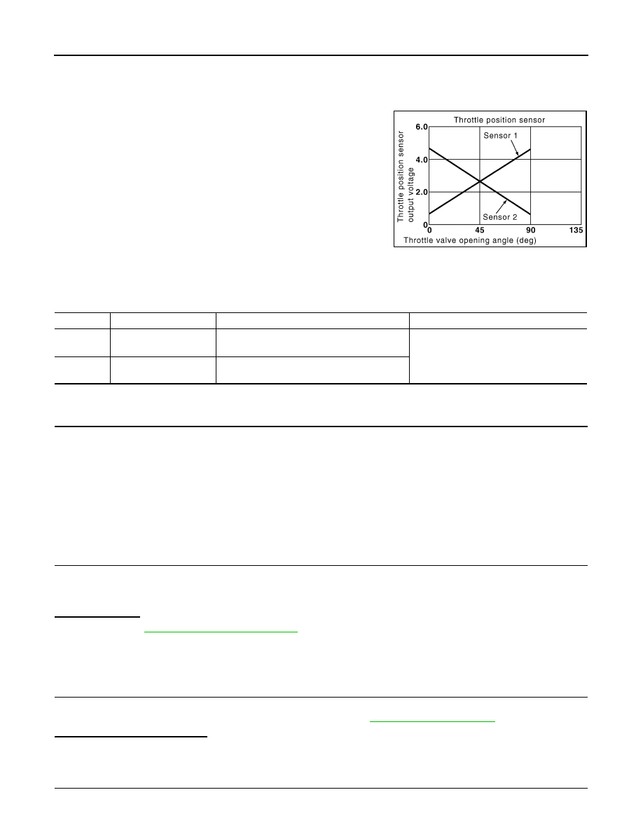
Electric throttle control actuator consists of throttle control motor,

throttle position sensor, etc. The throttle position sensor responds to

the throttle valve movement. 

The throttle position sensor has two sensors. These sensors are a

kind of potentiometers which transform the throttle valve position into

output voltage, and emit the voltage signal to the ECM. In addition,

these sensors detect the opening and closing speed of the throttle

valve and feed the voltage signals to the ECM. The ECM judges the

current opening angle of the throttle valve from these signals and the

ECM controls the throttle control motor to make the throttle valve

opening angle properly in response to driving condition.

DTC Logic

INFOID:0000000004211478

DTC DETECTION LOGIC

DTC CONFIRMATION PROCEDURE

1.

PRECONDITIONING

If DTC Confirmation Procedure has been previously conducted, always perform the following before conduct-

ing the next test.

1. Turn ignition switch OFF and wait at least 10 seconds.

2. Turn ignition switch ON.

3. Turn ignition switch OFF and wait at least 10 seconds.

TESTING CONDITION:

Before performing the following procedure, confirm that battery voltage is more than 8V at idle.

>> GO TO 2.

2.

PERFORM DTC CONFIRMATION PROCEDURE

1. Turn ignition switch ON (READY).

2. Depress the accelerator pedal to start engine, then keep engine running for at least 1 second.

3. Check DTC.
Is DTC detected?

YES

>> Go to 

EC-240, "Diagnosis Procedure"

.

NO

>> INSPECTION END

Diagnosis Procedure

INFOID:0000000004211479

1.

CHECK GROUND CONNECTION

1. Turn ignition switch OFF.

2. Check ground connection E9. Refer to Ground Inspection in 

GI-45, "Circuit Inspection"

.

Is the inspection result normal?

YES

>> GO TO 2.

NO

>> Repair or replace ground connection.

2.

CHECK THROTTLE POSITION SENSOR 1 POWER SUPPLY CIRCUIT

1. Disconnect electric throttle control actuator harness connector.

PBIB0145E

DTC No.

Trouble diagnosis name

DTC detecting condition

Possible cause

P0222

Throttle position sensor 
1 circuit low input

An excessively low voltage from the TP sensor 
1 is sent to ECM.

• Harness or connectors

(TP sensor 1 circuit is open or shorted.)

• Electric throttle control actuator

(TP sensor 1)

P0223

Throttle position sensor 
1 circuit high input

An excessively high voltage from the TP sensor 
1 is sent to ECM.

P0222, P0223 TP SENSOR

EC-241

< COMPONENT DIAGNOSIS >

[QR25DE]

C

D

E

F

G

H

I

J

K

L

M

A

EC

N

P

O

2. Turn ignition switch ON.

3. Check the voltage between electric throttle control actuator har-

ness connector and ground.

Is the inspection result normal?

YES

>> GO TO 3.

NO

>> Repair open circuit or short to ground or short to power

in harness or connectors.

3.

CHECK THROTTLE POSITION SENSOR 1 GROUND CIRCUIT FOR OPEN AND SHORT

1. Turn ignition switch OFF.

2. Disconnect ECM harness connector.

3. Check the continuity between electric throttle control actuator harness connector and ECM harness con-

nector.

4. Also check harness for short to ground and short to power.
Is the inspection result normal?

YES

>> GO TO 4.

NO

>> Repair open circuit or short to ground or short to power in harness or connectors.

4.

CHECK THROTTLE POSITION SENSOR 1 INPUT SIGNAL CIRCUIT FOR OPEN AND SHORT

1. Check the continuity between electric throttle control actuator harness connector and ECM harness con-

nector.

2. Also check harness for short to ground and short to power.
Is the inspection result normal?

YES

>> GO TO 5.

NO

>> Repair open circuit or short to ground or short to power in harness or connectors.

5.

CHECK THROTTLE POSITION SENSOR

Refer to 

EC-242, "Component Inspection"

.

Is the inspection result normal?

YES

>> GO TO 7.

NO

>> GO TO 6.

6.

REPLACE ELECTRIC THROTTLE CONTROL ACTUATOR

1. Replace electric throttle control actuator.

2. Go to 

EC-15, "THROTTLE VALVE CLOSED POSITION LEARNING : Special Repair Requirement"

.

>> INSPECTION END

7.

CHECK INTERMITTENT INCIDENT

Refer to 

GI-42, "Intermittent Incident"

.

>> INSPECTION END

Electric throttle control actuator

Ground

Voltage

Connector

Terminal

F57

1

Ground

Approx. 5V

JMBIA1591ZZ

Electric throttle control actuator

ECM

Continuity

Connector

Terminal

Connector

Terminal

F57

4

F13

36

Existed

Electric throttle control actuator

ECM

Continuity

Connector

Terminal

Connector

Terminal

F57

2

F13

37

Existed

EC-242

< COMPONENT DIAGNOSIS >

[QR25DE]

P0222, P0223 TP SENSOR

Component Inspection

INFOID:0000000004362542

1.

CHECK THROTTLE POSITION SENSOR

1. Turn ignition switch OFF.

2. Reconnect all harness connectors disconnected.

3. Perform 

EC-15, "THROTTLE VALVE CLOSED POSITION LEARNING : Special Repair Requirement"

.

4. Turn ignition switch ON.

5. Set shift lever to D position. 

6. Check the voltage between ECM harness connector and

ground.

Is the inspection result normal?

YES

>> INSPECTION END

NO

>> GO TO 2.

2.

REPLACE ELECTRIC THROTTLE CONTROL ACTUATOR

1. Replace electric throttle control actuator.

2. Go to 

EC-242, "Special Repair Requirement"

.

>> INSPECTION END

Special Repair Requirement

INFOID:0000000004362543

1.

PERFORM THROTTLE VALVE CLOSED POSITION LEARNING

Refer to 

EC-15, "THROTTLE VALVE CLOSED POSITION LEARNING : Special Repair Requirement"

>> GO TO 2.

2.

PERFORM IDLE AIR VOLUME LEARNING

Refer to 

EC-16, "IDLE AIR VOLUME LEARNING : Special Repair Requirement"

>> END

ECM

Ground

Condition

Voltage

Connector

Terminal

F13

37

(TP sensor 

1 signal)

Ground

Accelerator 
pedal

Fully 
released

More than 0.36 V

Fully 
depressed

Less than 4.75 V

38

 (TP sensor 

2 signal)

Fully 
released

Less than 4.75 V

Fully 
depressed

More than 0.36 V

JMBIA1634ZZ

P0300, P0301, P0302, P0303, P0304 MISFIRE

EC-243

< COMPONENT DIAGNOSIS >

[QR25DE]

C

D

E

F

G

H

I

J

K

L

M

A

EC

N

P

O

P0300, P0301, P0302, P0303, P0304 MISFIRE

DTC Logic

INFOID:0000000004211482

DTC DETECTION LOGIC

When a misfire occurs, engine speed will fluctuate. If the engine speed fluctuates enough to cause the crank-

shaft position (CKP) sensor (POS) signal to vary, ECM can determine that a misfire is occurring.

The misfire detection logic consists of the following two conditions.
1. One Trip Detection Logic (Three Way Catalyst Damage) 

On the 1st trip, when a misfire condition occurs that can damage the three way catalyst (TWC) due to

overheating, the MIL will blink.

When a misfire condition occurs, the ECM monitors the CKP sensor signal every 200 engine revolutions

for a change.

When the misfire condition decreases to a level that will not damage the TWC, the MIL will turn off.

If another misfire condition occurs that can damage the TWC on a second trip, the MIL will blink.

When the misfire condition decreases to a level that will not damage the TWC, the MIL will remain on.

If another misfire condition occurs that can damage the TWC, the MIL will begin to blink again.

2. Two Trip Detection Logic (Exhaust quality deterioration)

For misfire conditions that will not damage the TWC (but will affect vehicle emissions), the MIL will only

light when the misfire is detected on a second trip. During this condition, the ECM monitors the CKP sen-

sor signal every 1,000 engine revolutions.

A misfire malfunction can be detected on any one cylinder or on multiple cylinders.

DTC CONFIRMATION PROCEDURE

1.

PRECONDITIONING

If DTC Confirmation Procedure has been previously conducted, always perform the following before conduct-

ing the next test.

1. Turn ignition switch OFF and wait at least 10 seconds.

2. Turn ignition switch ON.

3. Turn ignition switch OFF and wait at least 10 seconds.

>> GO TO 2.

2.

PERFORM DTC CONFIRMATION PROCEDURE-I

1. Activate “INSPECTION MODE 1” (

HBC-104

) to start engine, and warm up engine to normal operating

temperature.

2. Turn ignition switch OFF and wait at least 10 seconds.

3. Turn ignition switch ON.

4. Turn ignition switch OFF and wait at least 10 seconds.

5. Activate “INSPECTION MODE 1” (

HBC-104

) to start engine, then keep engine running for at least 15 min-

utes.

6. Check 1st trip DTC.

Sensor

Input signal to ECM

ECM function

Crankshaft position sensor (POS)

Engine speed

On board diagnosis of misfire

DTC No.

Trouble diagnosis name

DTC detecting condition

Possible cause

P0300

Multiple cylinder misfire detected

Multiple cylinder misfire.

• Improper spark plug
• Insufficient compression
• Incorrect fuel pressure
• The fuel injector circuit is open or shorted
• Fuel injector
• Intake air leak
• The ignition signal circuit is open or shorted
• Lack of fuel
• Signal plate
• A/F sensor 1
• Incorrect PCV hose connection

P0301

No.1 cylinder misfire detected

No. 1 cylinder misfires.

P0302

No. 2 cylinder misfire detected

No. 2 cylinder misfires.

P0303

No. 3 cylinder misfire detected

No. 3 cylinder misfires.

P0304

No. 4 cylinder misfire detected

No. 4 cylinder misfires.


Content   ..  312  313  314  315   ..