Nissan Altima HL32 Hybrid. Manual - part 287


  Index      Nissan     Nissan Altima HL32 Hybrid (2009 year) - Service and Repair Manual


Search            


Content   ..  285  286  287  288   ..


Nissan Altima HL32 Hybrid. Manual - part 287


EC-132

< COMPONENT DIAGNOSIS >

[QR25DE]

P0031, P0032 A/F SENSOR 1 HEATER

>> Repair or replace.

Component Inspection

INFOID:0000000004211371

1.

CHECK AIR FUEL RATIO (A/F) SENSOR 1

1. Turn ignition switch OFF.

2. Disconnect A/F sensor 1 harness connector.

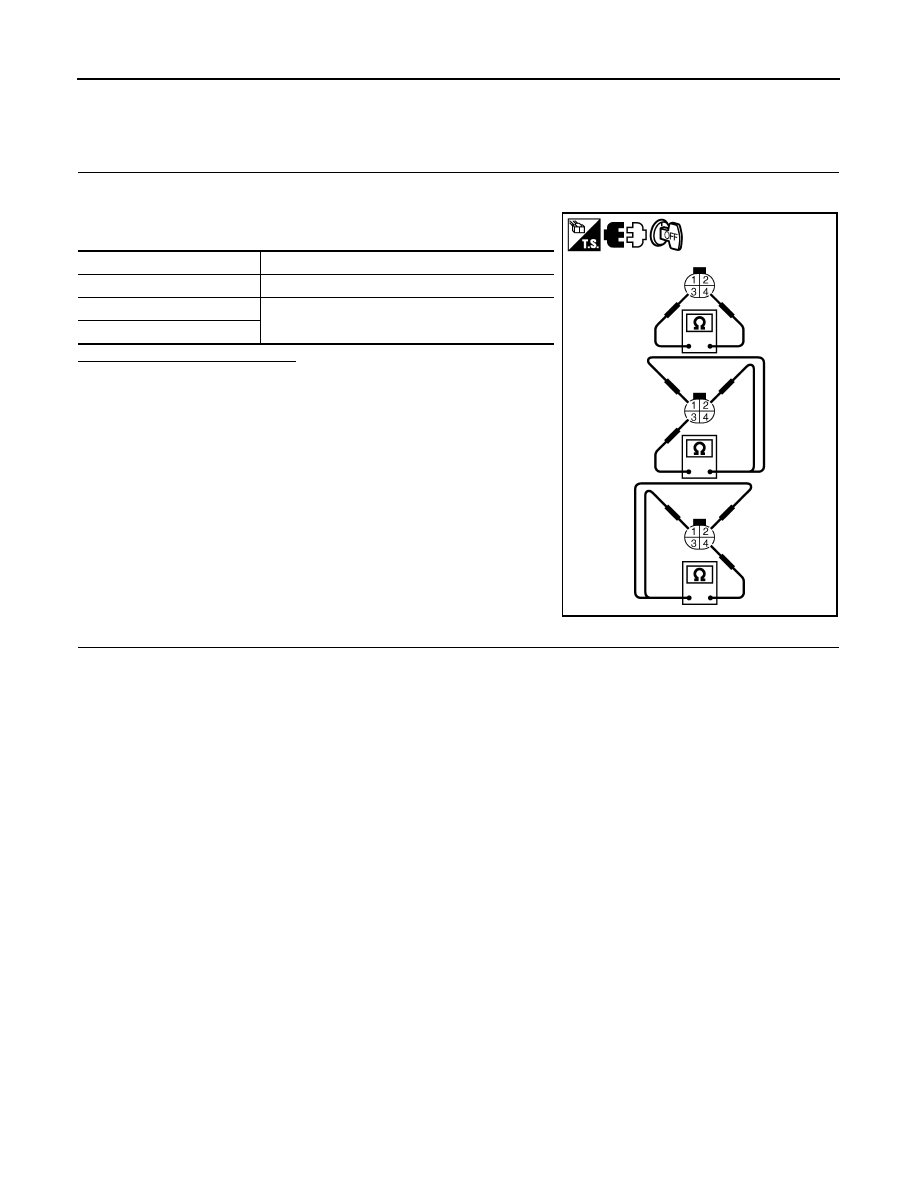
3. Check resistance between A/F sensor 1 terminals as follows.

Is the inspection result normal?

YES

>> INSPECTION END

NO

>> GO TO 2.

2.

REPLACE AIR FUEL RATIO (A/F) SENSOR 1

Replace air fuel ratio (A/F) sensor 1.

CAUTION:

• Discard any sensor which has been dropped from a height of more than 0.5 m (19.7 in) onto a hard

surface such as a concrete floor; use a new one.

• Before installing new sensor, clean exhaust system threads using oxygen sensor thread cleaner

[commercial service tool: (J-43897-18 or J-43897-12)] and approved anti-seize lubricant (commercial

service tool).

>> INSPECTION END

Terminals

Resistance

3 and 4

1.8 - 2.44 

Ω [at 25°C (77°F)]

3 and 1, 2

∞Ω

(Continuity should not exist)

4 and 1, 2

PBIB3309E

P0037, P0038 HO2S2 HEATER

EC-133

< COMPONENT DIAGNOSIS >

[QR25DE]

C

D

E

F

G

H

I

J

K

L

M

A

EC

N

P

O

P0037, P0038 HO2S2 HEATER

Description

INFOID:0000000004211372

SYSTEM DESCRIPTION

The ECM performs ON/OFF control of the heated oxygen sensor 2 heater corresponding to the engine speed,

amount of intake air and engine coolant temperature. 

OPERATION

DTC Logic

INFOID:0000000004211373

DTC DETECTION LOGIC

DTC CONFIRMATION PROCEDURE

1.

PRECONDITIONING

If DTC Confirmation Procedure has been previously conducted, always perform the following before conduct-

ing the next test.

1. Turn ignition switch OFF and wait at least 10 seconds.

2. Turn ignition switch ON.

3. Turn ignition switch OFF and wait at least 10 seconds.

TESTING CONDITION:

Before performing the following procedure, confirm that battery voltage is more than 11V at idle.

>> GO TO 2.

2.

PERFORM DTC CONFIRMATION PROCEDURE

1. Activate “INSPECTION MODE 1” (

HBC-104

) to start engine, and warm up engine to normal operating

temperature.

2. Turn ignition switch OFF and wait at least 10 seconds.

3. Turn ignition switch ON.

Sensor

Input signal to ECM

ECM function

Actuator

Camshaft position sensor (PHASE)
Crankshaft position sensor (POS)

Engine speed

Heated oxygen sensor 2 
heater control

Heated oxygen sensor 2 heater

Engine coolant temperature sensor

Engine coolant temperature

Mass air flow sensor

Amount of intake air

Engine speed

Heated oxygen sensor 2 heater

Above 3,600 rpm

OFF

More than 3 minutes after engine stopped.

Below 3,600 rpm after the following conditions are met.
• Engine: After warming up
• Driving for 3 minutes at a speed of 80 km/h (50 MPH) or more

(Keep the vehicle speed as steady as possible during the cruis-
ing.)

ON

DTC No.

Trouble diagnosis 

name

DTC detecting condition

Possible cause

P0037

Heated oxygen 
sensor 2 heater 
control circuit low

The current amperage in the heated oxygen sen-
sor 2 heater circuit is out of the normal range.
(An excessively low voltage signal is sent to ECM 
through the heated oxygen sensor 2 heater.)

• Harness or connectors

(The heated oxygen sensor 2 heater circuit is 
open or shorted.)

• Heated oxygen sensor 2 heater

P0038

Heated oxygen 
sensor 2 heater 
control circuit high

The current amperage in the heated oxygen sen-
sor 2 heater circuit is out of the normal range.
(An excessively high voltage signal is sent to ECM 
through the heated oxygen sensor 2 heater.)

• Harness or connectors

(The heated oxygen sensor 2 heater circuit is 
shorted.)

• Heated oxygen sensor 2 heater

EC-134

< COMPONENT DIAGNOSIS >

[QR25DE]

P0037, P0038 HO2S2 HEATER

4. Turn ignition switch OFF and wait at least 10 seconds.

5. Turn ignition switch ON (READY).

6. Drive vehicle at a speed of 80 km/h (50 MPH) or more for at least 3 consecutive minutes.

CAUTION:

Always drive vehicle in safe manner according to traffic conditions and obey all traffic laws.

NOTE:

Keep the vehicle speed as steady as possible during the cruising.

7. Check 1st trip DTC.
Is 1st trip DTC detected?

YES

>> Go to 

EC-134, "Diagnosis Procedure"

.

NO

>> INSPECTION END

Diagnosis Procedure

INFOID:0000000004211374

1.

CHECK GROUND CONNECTION

1. Turn ignition switch OFF.

2. Check ground connection E9. Refer to Ground Inspection in 

GI-45, "Circuit Inspection"

.

Is the inspection result normal?

YES

>> GO TO 2.

NO

>> Repair or replace ground connection.

2.

CHECK HO2S2 POWER SUPPLY CIRCUIT

1. Disconnect heated oxygen sensor 2 harness connector.

2. Turn ignition switch ON.

3. Check the voltage between HO2S2 harness connector and

ground.

Is the inspection result normal?

YES

>> GO TO 4.

NO

>> GO TO 3.

3.

DETECT MALFUNCTIONING PART

Check the following.

• IPDM E/R connector F10

• 15A fuse (No. 37)

• Harness for open or short between heated oxygen sensor 2 and fuse

>> Repair open circuit or short to ground or short to power in harness or connectors.

4.

CHECK HO2S2 OUTPUT SIGNAL CIRCUIT FOR OPEN AND SHORT

1. Turn ignition switch OFF.

2. Disconnect ECM harness connector.

3. Check the continuity between HO2S2 harness connector and ECM harness connector.

4. Also check harness for short to ground and short to power.
Is the inspection result normal?

YES

>> GO TO 5.

NO

>> Repair open circuit or short to ground or short to power in harness or connectors.

HO2S2

Ground

Voltage

Connector

Terminal

F42

2

Ground

Battery voltage

MBIB0186E

HO2S2

ECM

Continuity

Connector

Terminal

Connector

Terminal

F42

3

F14

13

Existed

P0037, P0038 HO2S2 HEATER

EC-135

< COMPONENT DIAGNOSIS >

[QR25DE]

C

D

E

F

G

H

I

J

K

L

M

A

EC

N

P

O

5.

CHECK HEATED OXYGEN SENSOR 2 HEATER

Refer to 

EC-135, "Component Inspection"

.

Is the inspection result normal?

YES

>> GO TO 7.

NO

>> GO TO 6.

6.

REPLACE HEATED OXYGEN SENSOR 2

Replace heated oxygen sensor 2.

CAUTION:

• Discard any sensor which has been dropped from a height of more than 0.5 m (19.7 in) onto a hard

surface such as a concrete floor; use a new one.

• Before installing new sensor, clean exhaust system threads using oxygen sensor thread cleaner

[commercial service tool: (J-43897-18 or J-43897-12)] and approved anti-seize lubricant (commercial

service tool).

>> INSPECTION END

7.

CHECK INTERMITTENT INCIDENT

Refer to 

GI-42, "Intermittent Incident"

.

>> INSPECTION END

Component Inspection

INFOID:0000000004211375

1.

CHECK HEATED OXYGEN SENSOR 2 HEATER

1. Turn ignition switch OFF.

2. Disconnect heated oxygen sensor 2 harness connector.

3. Check resistance between HO2S2 terminals as follows.

Is the inspection result normal?

YES

>> INSPECTION END

NO

>> GO TO 2.

2.

REPLACE HEATED OXYGEN SENSOR 2

Replace heated oxygen sensor 2.

CAUTION:

• Discard any sensor which has been dropped from a height of more than 0.5 m (19.7 in) onto a hard

surface such as a concrete floor; use a new one.

Terminals

Resistance

2 and 3

3.4 - 4.4 

Ω [at 25°C (77°F)]

1 and 2, 3, 4

∞Ω

(Continuity should not exist)

4 and 1, 2, 3

PBIB3310E


Content   ..  285  286  287  288   ..