Nissan Altima HL32 Hybrid. Manual - part 220


  Index      Nissan     Nissan Altima HL32 Hybrid (2009 year) - Service and Repair Manual


Search            


Content   ..  218  219  220  221   ..


Nissan Altima HL32 Hybrid. Manual - part 220


DOOR LOCK ACTUATOR

DLK-101

< COMPONENT DIAGNOSIS >

C

D

E

F

G

H

I

J

L

M

A

B

DLK

N

O

P

DOOR LOCK ACTUATOR

DRIVER SIDE
DRIVER SIDE : Description

INFOID:0000000004215710

Locks/unlocks the door with the signal from BCM.

DRIVER SIDE : Component Function Check

INFOID:0000000004215711

1.

CHECK FUNCTION

1. Use CONSULT-III to perform Active Test (“DOOR LOCK”).

2. Touch “ALL LOCK” or “ALL UNLOCK” to check that it works normally.
Is the inspection result normal?

YES

>> Door lock actuator is OK.

NO

>> Refer to 

DLK-101, "DRIVER SIDE : Diagnosis Procedure"

.

DRIVER SIDE : Diagnosis Procedure

INFOID:0000000004215712
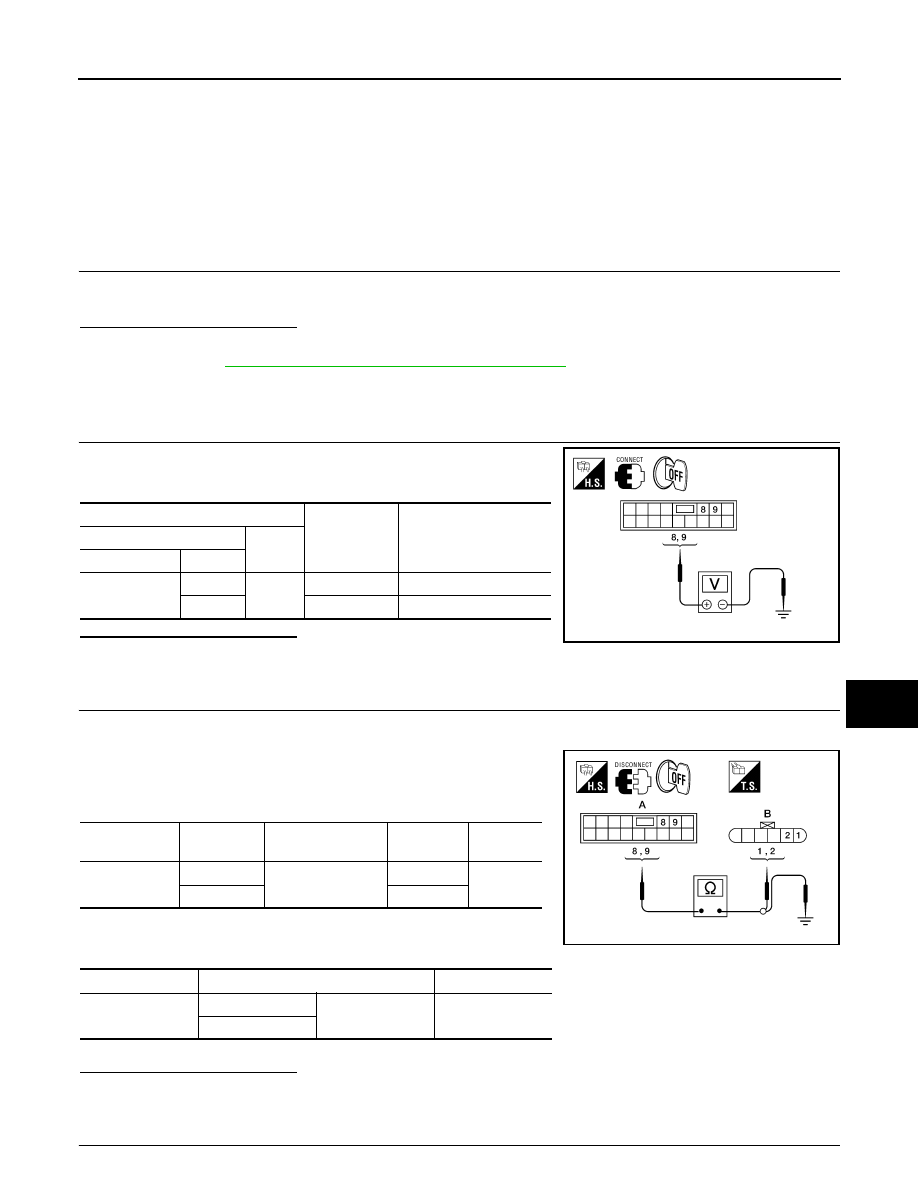
1.

CHECK OUTPUT SIGNAL

Check voltage between BCM connector M17 terminals 8, 9 and

ground.

Is the inspection result normal?

YES

>> GO TO 3

NO

>> GO TO 2

2.

CHECK DOOR LOCK ACTUATOR CIRCUIT

1. Turn ignition switch OFF.

2. Disconnect BCM and front door lock actuator driver side connector.

3. Check continuity between BCM connector M17 (A) terminals 8,

9 and front door lock actuator driver side connector D10 (B) ter-

minals 1, 2.

4. Check continuity between BCM connector M17 (A) terminals 8,

9 and ground.

Is the inspection result normal?

YES

>> Replace front door lock actuator LH.

NO

>> Repair or replace harness.

3.

CHECK INTERMITTENT INCIDENT

Terminals

Condition of 

door lock and 
unlock switch

Voltage (V)

(Approx.)

(+)

(–)

BCM connector

Terminal

M17

8

Ground

Lock

→ Battery voltage → 0

9

Unlock

→ Battery voltage → 0

ALKIA0401ZZ

BCM connector

Terminal

Door lock actuator 

connector

Terminal

Continuity 

A: M17

8

B: D10

1

Yes

9

2

BCM connector

Terminal

Continuity 

A: M17

8

Ground

No

9

ALKIA0402ZZ

DLK-102

< COMPONENT DIAGNOSIS >

DOOR LOCK ACTUATOR

Refer to 

GI-42, "Intermittent Incident"

.

>> Inspection End.

PASSENGER SIDE
PASSENGER SIDE : Description

INFOID:0000000004215713

Locks/unlocks the door with the signal from BCM.

PASSENGER SIDE : Component Function Check

INFOID:0000000004215714

1.

CHECK FUNCTION

1. Use CONSULT-III to perform Active Test (“DOOR LOCK”).

2. Touch “ALL LOCK” or “ALL UNLOCK” to check that it works normally.
Is the inspection result normal?

YES

>> Door lock actuator is OK.

NO

>> Refer to 

DLK-102, "PASSENGER SIDE : Diagnosis Procedure"

.

PASSENGER SIDE : Diagnosis Procedure

INFOID:0000000004215715

1.

CHECK DOOR LOCK ACTUATOR SIGNAL

Check voltage between BCM connector and ground.

Is the inspection result normal?

YES

>> GO TO 3

NO

>> GO TO 2

2.

CHECK DOOR LOCK ACTUATOR CIRCUIT

1. Disconnect BCM and front door lock actuator RH connectors. 

2. Check continuity between BCM connector M17 (A) terminals 5,

8 and front door lock actuator RH D108 (B) terminals 5, 6.

3. Check continuity between BCM connector M17 (A) terminals 5,

8 and ground.

Is the inspection result normal?

YES

>> Replace front door lock actuator RH.

NO

>> Repair or replace harness.

3.

CHECK INTERMITTENT INCIDENT

Terminals

Condition of 

door lock and 
unlock switch

Voltage (V)

(Approx.)

(+)

(–)

BCM connector

Terminal

M17

8

Ground

Lock

→ Battery voltage → 0

5

Unlock

→ Battery voltage → 0

ALKIA0403ZZ

BCM connector

Terminal

Front door lock 

actuator RH 

connector

Terminal

Continuity 

A: M17

8

B: D108

5

Yes

5

6

BCM connector

Terminal

Continuity 

A: M17

8

Ground

No

5

ALKIA0404ZZ

DOOR LOCK ACTUATOR

DLK-103

< COMPONENT DIAGNOSIS >

C

D

E

F

G

H

I

J

L

M

A

B

DLK

N

O

P

Refer to 

GI-42, "Intermittent Incident"

.

>> Inspection End.

REAR LH
REAR LH : Description

INFOID:0000000004215716

Locks/unlocks the door with the signal from BCM.

REAR LH : Component Function Check

INFOID:0000000004215717

1.

CHECK FUNCTION

1. Use CONSULT-III to perform Active Test (“DOOR LOCK”).

2. Touch “ALL LOCK” or “ALL UNLOCK” to check that it works normally.
Is the inspection result normal?

YES

>> Door lock actuator is OK.

NO

>> Refer to 

DLK-103, "REAR LH : Diagnosis Procedure"

.

REAR LH : Diagnosis Procedure

INFOID:0000000004215718

1.

CHECK DOOR LOCK ACTUATOR SIGNAL

Check voltage between BCM connector M17 terminals 8, 10 and ground.

Check trunk lamp switch.

Is the inspection result normal?

YES

>> GO TO 3

NO

>> GO TO 2

2.

CHECK DOOR LOCK ACTUATOR CIRCUIT

1. Disconnect BCM and rear door lock actuator LH connectors. 

2. Check continuity between BCM connector M17 (A) terminals 8,

10 and rear door lock actuator LH connectors D205 (B) termi-

nals 1, 2.

3. Check continuity between BCM connector and ground.

Is the inspection result normal?

YES

>> Replace rear door lock actuator LH.

NO

>> Repair or replace harness.

3.

CHECK INTERMITTENT INCIDENT

Terminals

Condition of 

door lock and 
unlock switch

Voltage (V)

(Approx.)

(+)

(–)

BCM connector

Terminal

M17

8

Ground

Lock

→ Battery voltage → 0

10

Unlock

→ Battery voltage → 0

ALKIA0405ZZ

BCM connector

Terminal

Door lock actuator 

connector

Terminal

Continuity 

A: M17

8

B: D205

1

Yes

10

2

BCM connector

Terminal

Continuity 

A: M17

8

Ground

No

10

ALKIA0406ZZ

DLK-104

< COMPONENT DIAGNOSIS >

DOOR LOCK ACTUATOR

Refer to 

GI-42, "Intermittent Incident"

.

>> Inspection End.

REAR RH
REAR RH : Description

INFOID:0000000004215719

Locks/unlocks the door with the signal from BCM.

REAR RH : Component Function Check

INFOID:0000000004215720

1.

CHECK FUNCTION

1. Use CONSULT-III to perform Active Test (“DOOR LOCK”).

2. Touch “ALL LOCK” or “ALL UNLOCK” to check that it works normally.
Is the inspection result normal?

YES

>> Door lock actuator is OK.

NO

>> Refer to 

DLK-104, "REAR RH : Diagnosis Procedure"

.

REAR RH : Diagnosis Procedure

INFOID:0000000004215721

1.

CHECK DOOR LOCK ACTUATOR SIGNAL

Check voltage between BCM connector M17 terminals 8, 10 and

ground.

Is the inspection result normal?

YES

>> GO TO 3

NO

>> GO TO 2

2.

CHECK DOOR LOCK ACTUATOR CIRCUIT

1. Disconnect BCM and rear door lock actuator RH connectors. 

2. Check continuity between BCM connector M17 (A) terminals 8,

10 and rear door lock actuator RH connector D305 (B) terminals

5, 6. 

3. Check continuity between BCM connector and ground.

Is the inspection result normal?

YES

>> Replace rear door lock actuator RH.

NO

>> Repair or replace harness.

3.

CHECK INTERMITTENT INCIDENT

Terminals

Condition of 

door lock and 
unlock switch

Voltage (V)

(Approx.)

(+)

(–)

BCM connector

Terminal

M17

8

Ground

Lock

→ Battery voltage → 0

10

Unlock

→ Battery voltage → 0

ALKIA0405ZZ

BCM connector

Terminal

Door lock actuator 

connector

Terminal

Continuity 

A: M17

8

B: D305

5

Yes

10

6

BCM connector

Terminal

Continuity 

A: M17

8

Ground

No

10

ALKIA0407ZZ


Content   ..  218  219  220  221   ..