Nissan Altima HL32 Hybrid. Manual - part 180


  Index      Nissan     Nissan Altima HL32 Hybrid (2009 year) - Service and Repair Manual


Search            


Content   ..  178  179  180  181   ..


Nissan Altima HL32 Hybrid. Manual - part 180


WATER CONTROL VALVE

CO-23

< ON-VEHICLE REPAIR >

[QR25DE]

C

D

E

F

G

H

I

J

K

L

M

A

CO

N

P

O

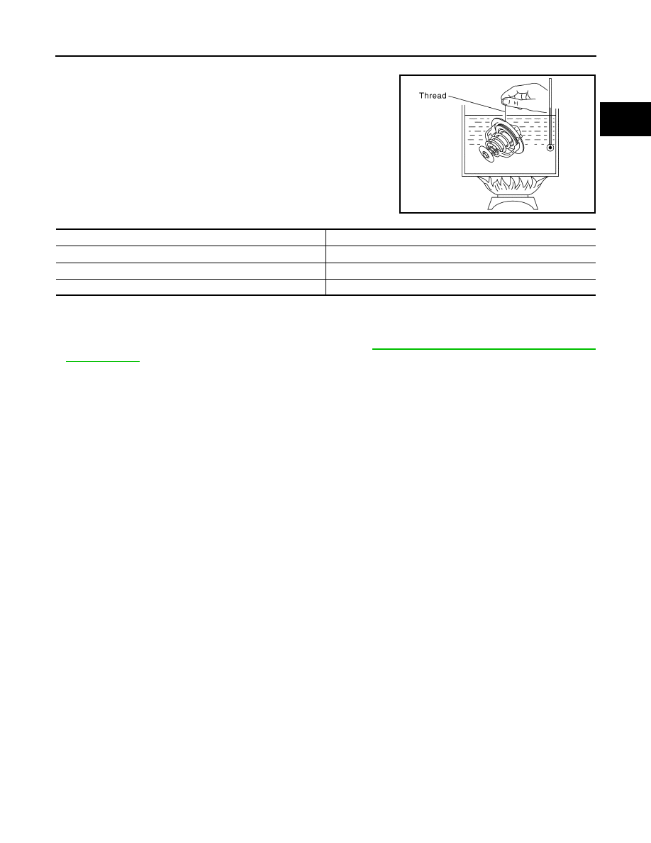
INSPECTION AFTER REMOVAL

• Place a thread so that it is caught in the valve of the water control

valve. Immerse fully in a container filled with water. Heat while stir-

ring. 

• The valve opening temperature is the temperature at which the

valve opens and the falls from the thread.

• Continue heating. Check the full-open lift amount.

NOTE:

The full-open lift amount standard temperature for the water con-

trol valve is the reference value.

•  After checking the full-open lift amount, lower the water tempera-

ture and check the valve closing temperature. 

Standard values

INSTALLATION

Installation is in the reverse order of removal.

• Install the engine coolant temperature sensor.

Use Genuine RTV Silicone Sealant or equivalent. Refer to 

GI-15, "Recommended Chemical Products

and Sealants"

.

• Install the water control valve with the whole circumference of the flange part fitting securely inside the rub-

ber ring. 

• Install the water control valve with the up-mark facing up and the frame center part facing upwards. The

position deviation may be within the range of 

±10°.

• Use a new gasket and O-ring for installation.

SLC252B

Water Control Valve 

Standard Value

Valve opening temperature

93.5

° - 96.5°C (200° - 206°F)

Full-open lift amount

More than 8 mm / 108

°C (0.315 in / 226° F)

Valve closing temperature

90

°C (194° F) or higher

CO-24

< SERVICE DATA AND SPECIFICATIONS (SDS) 

[QR25DE]

SERVICE DATA AND SPECIFICATIONS (SDS)

SERVICE DATA AND SPECIFICATIONS (SDS)

SERVICE DATA AND SPECIFICATIONS (SDS)

Capacity

INFOID:0000000004211297

 (US qt, Imp qt)

Thermostat

INFOID:0000000004211298

Water Control Valve

INFOID:0000000004211299

Radiator

INFOID:0000000004211300

Unit: kPa (kg / cm

2

, psi)

Coolant capacity (With reservoir tank at MAX level)

                                      7.7 (8 1/8, 6 3/4)

Valve opening temperature

80.5 - 83.5

°C (177 - 182°F)

Full-open lift amount

More than 8 mm / 95

°C (0.315 in / 203°F)

Valve closing temperature

77

°C (171°F) or higher

Valve opening temperature

93.5 - 96.5

°C (200 - 206°F)

Full-open lift amount

More than 8 mm / 108

°C (0.315 in / 226°F)

Valve closing temperature

90

°C (194°F) or higher

Cap relief pressure

Standard

122 - 152 (1.2 - 1.5, 18 - 22)

Limit

107 (1.1, 16)

Leakage test pressure

157 (1.6, 23)

DEF-1

DRIVER CONTROLS

C

D

E

F

G

H

I

J

K

M

SECTION 

DEF

A

B

DEF

N

O

P

CONTENTS

DEFOGGER

BASIC INSPECTION  ....................................

3

DIAGNOSIS AND REPAIR WORKFLOW  ..........

3

Work Flow  .................................................................

3

FUNCTION DIAGNOSIS ...............................

6

REAR WINDOW DEFOGGER SYSTEM .............

6

System Diagram ........................................................

6

System Description  ...................................................

6

Component Parts Location ........................................

7

Component Description .............................................

7

DIAGNOSIS SYSTEM (BCM)  .............................

9

COMMON ITEM ...........................................................

9

COMMON ITEM : CONSULT-III Function (BCM - 
COMMON ITEM) .....................................................
..

9

REAR WINDOW DEFOGGER .....................................

9

REAR WINDOW DEFOGGER : CONSULT-III 
Function (BCM - REAR DEFOGGER)  ....................
..

9

COMPONENT DIAGNOSIS .........................

10

REAR WINDOW DEFOGGER SWITCH  ............

10

Description ..............................................................

10

Component Function Check ....................................

10

Diagnosis Procedure ...............................................

10

REAR WINDOW DEFOGGER RELAY  ..............

11

Description ..............................................................

11

Component Function Check ....................................

11

Diagnosis Procedure ...............................................

11

Component Inspection  ............................................

12

REAR WINDOW DEFOGGER POWER SUP-
PLY AND GROUND CIRCUIT ............................

13

Description ..............................................................

13

Component Function Check ....................................

13

Diagnosis Procedure ...............................................

13

Component Inspection  ............................................

14

DRIVER SIDE DOOR MIRROR DEFOGGER ...

15

Description ...............................................................

15

Component Function Check  ....................................

15

Diagnosis Procedure  ...............................................

15

Component Inspection .............................................

16

PASSENGER SIDE DOOR MIRROR DEFOG-
GER ...................................................................

17

Description ...............................................................

17

Component Function Check  ....................................

17

Diagnosis Procedure  ...............................................

17

Component Inspection .............................................

18

ECU DIAGNOSIS .........................................

19

BCM (BODY CONTROL MODULE)  .................

19

Reference Value ......................................................

19

Terminal Layout .......................................................

23

Physical Values  .......................................................

24

Wiring Diagram - Defogger Control System  ............

42

SYMPTOM DIAGNOSIS  ..............................

49

REAR WINDOW DEFOGGER AND DOOR 
MIRROR DEFOGGER DO NOT OPERATE.  ....

49

Diagnosis Procedure  ...............................................

49

REAR WINDOW DEFOGGER DOES NOT 
OPERATE BUT BOTH OF DOOR MIRROR 
DEFOGGER OPERATE. ...................................

50

Diagnosis Procedure  ...............................................

50

BOTH DOORS MIRROR DEFOGGER DON’T 
OPERATE BUT REAR WINDOW DEFOG-
GER OPERATES  ..............................................

51

Diagnosis Procedure  ...............................................

51

DRIVER SIDE DOOR MIRROR DEFOGGER 
DOES NOT OPERATE. .....................................

52

Diagnosis Procedure  ...............................................

52


Content   ..  178  179  180  181   ..