Nissan Altima HL32 Hybrid. Manual - part 151


  Index      Nissan     Nissan Altima HL32 Hybrid (2009 year) - Service and Repair Manual


Search            


Content   ..  149  150  151  152   ..


Nissan Altima HL32 Hybrid. Manual - part 151


ABS ACTUATOR AND ELECTRIC UNIT (CONTROL UNIT)

BRC-169

< ECU DIAGNOSIS >

[VDC/TCS/ABS]

C

D

E

G

H

I

J

K

L

M

A

B

BRC

N

O

P

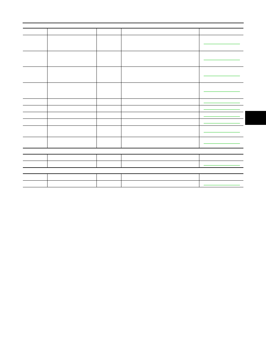
TEST MODE DTC of ABS:

TEST MODE DTC of VDC:

TEST MODE DTC of Electronically controlled Brake:

DTC code

Detection item

INF code

Trouble area

Reference page

C1271

FR SPD OUTPUT

1.

Front wheel sensor RH

2.

Snesor installation

3.

Wheel sensor rotor

BRC-57, "Description"

C1272

FL SPD OUTPUT

1.

Front wheel sensor LH

2.

Snesor installation

3.

Wheel sensor rotor

BRC-57, "Description"

C1273

RR SPD OUTPUT

1.

Rear wheel sensor RH

2.

Snesor installation

3.

Wheel sensor rotor

BRC-62, "Description"

C1274

RL SPD OUTPUT

1.

Rear wheel sensor LH

2.

Snesor installation

3.

Wheel sensor rotor

BRC-62, "Description"

C1275

FR SPD OUTPUT HI

Wheel sensor rotor

BRC-77, "Description"

C1276

FL SPD OUTPUT HI

Wheel sensor rotor

BRC-77, "Description"

C1277

RR SPD OUTPUT HI

Wheel sensor rotor

BRC-77, "Description"

C1278

RL SPD OUTPUT HI

Wheel sensor rotor

BRC-77, "Description"

C1279

G SEN OUTPUT

1.

Yaw rate/side/decel G sensor

2.

Sensor installation

BRC-68, "Description"

C1281

MC SENSOR OUTPUT

1.

Stop lamp switch

2.

Master cylinder pressure sensor

BRC-68, "Description"

DTC code

Detection item

INF code

Trouble area

Reference page

C0371

YAW SEN OUTPUT

Yaw rate/side/decel G sensor

BRC-68, "Description"

DTC code

Detection item

INF code

Trouble area

Reference page

C1346

STROKE SEN CALIB

Brake stroke sensor

BRC-91, "Description"

BRC-170

< SYMPTOM DIAGNOSIS >

[VDC/TCS/ABS]

VDC/TCS/ABS SYMPTOMS

SYMPTOM DIAGNOSIS

VDC/TCS/ABS SYMPTOMS

Symptom Table

INFOID:0000000004212741

PROBLEM SYMPTOMS TABLE

If there are no DTCs output but the problem still occurs, check the circuits for each problem symptom in the

order given in the table below and proceed to the relevant troubleshooting page.

CAUTION:

When replacing the brake ECU, sensor, etc., make sure that the ignition switch is turned OFF, the stop

lamp switch is off, and 2 minutes have elapsed since the driver

s door was closed.

NOTE:

• Inspect the fuse and relay before investigating the suspected areas shown in the table below.

• Inspect each malfunctioning circuit in numerical order for the corresponding symptom.

• Since the oil passage is blocked off by the master cut solenoid during Electronically Controlled Brake con-

trol, there is no kickback (vibration) to the brake pedal, creating a quiet operating sound even while the ABS

is operating.

Symptom

Suspected area

Reference page

ABS and/or EBD does not operate

Use a chassis dynamometer, etc. to check 
the Electronically Controlled Brake opera-
tion.

Check the DTC again and make sure that 
the normal system code is output.

IG power source circuit

BRC-83, "Description"

Front wheel sensor circuit

BRC-57, "Description"

Rear wheel snesor circuit

BRC-62, "Description"

Check the brake actuator assembly with 
the CONSULT-III. (Check brake actuator 
assembly operation using the Active Test 
function.) If abnormal, check the hydraulic 
circuit for leakage.

BRC-194, "Inspection"

If the symptoms still occur even after the 
above circuits in suspected areas have 
been inspected and proved to be normal, 
replace the brake ECU.

ABS and/or EBD does not operate efficient-
ly

Check the DTC again and make sure that 
the normal system code is output.

Front wheel sensor circuit

BRC-57, "Description"

Rear wheel sensor circuit

BRC-62, "Description"

Check the brake actuator assembly with 
the CONSULT-III. (Check brake actuator 
assembly operation using the Active Test 
function.) If abnormal, check the hydraulic 
circuit for leakage.

BRC-194, "Inspection"

If the symptoms still occur even after the 
above circuits in suspected areas have 
been inspected and proved to be normal, 
replace the brake ECU.

ABS warning lamp abnormal (Remains on)

ABS warning lamp circuit

BRC-172, "Description"

Brake ECU

BRC-111, "Description"

ABS warning lamp abnormal (Does not 
come on)

ABS warning lamp circuit

BRC-174, "Description"

Brake ECU

BRC-111, "Description"

Brake warning lamp (Remains on)

Brake fluid level switch circuit

BRC-177, "Description"

Brake ECU

BRC-111, "Description"

VDC/TCS/ABS SYMPTOMS

BRC-171

< SYMPTOM DIAGNOSIS >

[VDC/TCS/ABS]

C

D

E

G

H

I

J

K

L

M

A

B

BRC

N

O

P

Brake warning lamp (Does not come on)

Brake fluid level switch circuit

BRC-181, "Description"

Brake ECU

BRC-111, "Description"

VDC and/or TCS does not operate

Check that traction control has not operat-
ed by carrying out diagnosis.

Check the DTC again and make sure that 
the normal system code is output.

IG power source circuit

BRC-83, "Description"

Check the hydraulic circuit for leakage

Front wheel sensor circuit

BRC-57, "Description"

Rear wheel sensor circuit

BRC-62, "Description"

Yaw rate/side/decel G sensor circuit

BRC-68, "Description"

Steering angle sensor circuit

BRC-75, "Description"

If the symptoms still occur even after the 
above circuits in suspected areas have 
been inspected and proved to be normal, 
replace the brake ECU.

Electronically Controlled Brake warning 
lamp abnormal (Remains on)

Electronically Controlled Brake warning 
lamp circuit

BRC-182, "Description"

Brake ECU

BRC-111, "Description"

Electronically Controlled Brake warning 
lamp abnormal (Does not come on)

Electronically Controlled Brake warning 
lamp circuit

BRC-183, "Description"

Brake ECU

BRC-111, "Description"

VDC warning abnormal (Remain on)

VDC warning lamp circuit

BRC-175, "Description"

Brake ECU

BRC-111, "Description"

VDC warning abnormal (Does not come 
on)

VDC warning lamp circuit

BRC-176, "Description"

Brake ECU

BRC-111, "Description"

SLIP indicator lamp abnormal (Remains 
on)

SLIP indicator lamp circuit

BRC-185, "Description"

Brake ECU

BRC-111, "Description"

SLIP indicator lamp abnormal (Does not 
come on)

SLIP indicator lamp circuit

BRC-186, "Description"

Brake ECU

BRC-111, "Description"

DTC check cannot be done

Check the DTC again and make sure that 
the normal system code is output.

TC and CG terminal circuit

If the symptoms still occur even after the 
above circuit in suspected areas has been 
inspected and proved to be normal, replace 
the brake ECU.

Sensor check cannot be done

TS and CG terminal circuit

Brake ECU

BRC-111, "Description"

Brake warning buzzer abnormal

Brake warning buzzer

BRC-187, "Description"

Brake ECU

BRC-111, "Description"

Symptom

Suspected area

Reference page

BRC-172

< SYMPTOM DIAGNOSIS >

[VDC/TCS/ABS]

ABS WARNING LAMP REMAINS ON

ABS WARNING LAMP REMAINS ON

Description

INFOID:0000000004212742

The brake ECU is connected to the combination meter with CAN communication via HV ECU. If any of the fol-

lowing is detected, the ABS warning lamp remains on.

• The brake ECU connectors are disconnected from the brake ECU.

• There is a malfunction in the brake ECU internal circuit or in the HV ECU.

• There is an open in the harness between the combination meter, HV ECU and the brake ECU.

NOTE:

In some cases, the CONSULT-III cannot be used when the brake ECU is abnormal.

Diagnosis Procedure

INFOID:0000000004212743

NOTE:

If a malfunction was detected in wheel sensor during the last travel, ABS warning lamp may remains ON until

the wheel sensor can be checked that it is normal at 10 km/h (6 MPH) during the next travel.

CAUTION:

When replacing the brake ECU, perform initialization of linear solenoid valve and calibration.

1.

CHECK CAN COMMUNICATION SYSTEM

Check if the CAN communication system DTC is output.

Result

A

>> GO  TO  2.

B

>> Inspect CAN communication system.

2.

CHECK IF BRAKE ECU CONNECTOR IS SECURELY CONNECTED

Check if the brake ECU connector is securely connected.

NOTE:

The connector should be securely connected.
Is the inspection result normal?

YES

>> GO TO 3.

NO

>> Connect connector to ECU correctly.

3.

CHECK AUXILIARY BATTERY

Check the auxiliary battery voltage.

Is the inspection result normal?

YES

>> GO TO 4.

NO

>> Charge or replace auxiliary battery.

4.

INSPECT BRAKE ECU (IG1 TERMINAL)

1. Disconnect the brake ECU connector.

2. Turn the ignition switch ON.

Condition

Proceed to

DTC is not output.

A

DTC is output.

B

Standard voltage : 11 to 14 V


Content   ..  149  150  151  152   ..