Content .. 1084 1085 1086 1087 ..
Nissan Altima HL32 Hybrid. Manual - part 1086
VTL-24
< ON-VEHICLE REPAIR >
DUCTS AND GRILLES
Grilles
CENTER VENTILATOR GRILLES
CENTER VENTILATOR GRILLES : Removal and Installation
INFOID:0000000004215250
REMOVAL
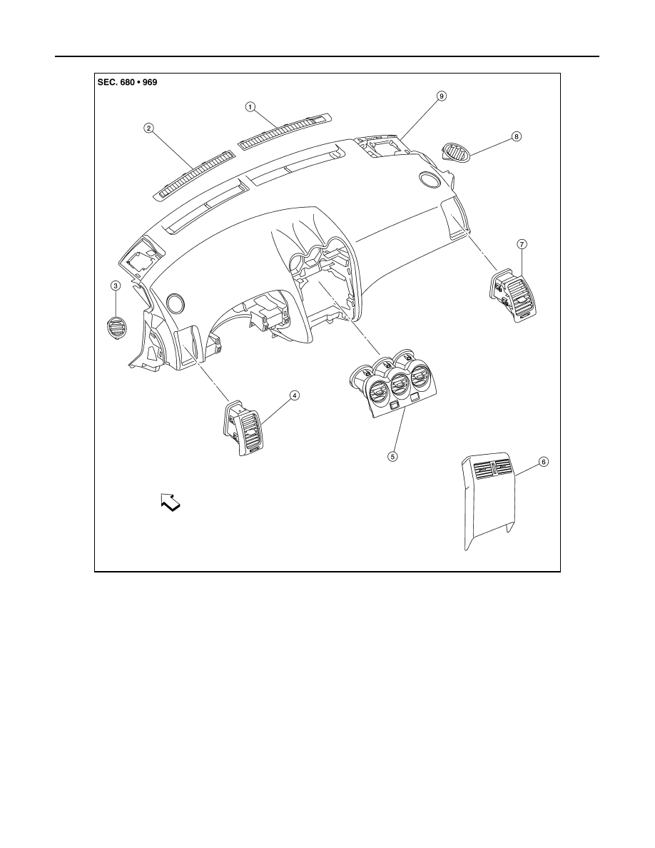
ALIIA0024ZZ
1.
Front defroster grille (RH)
2.
Front defroster grille (LH)
3.
Side defroster grille (LH)
4.
Side ventilator grille (LH)
5.
Center ventilator grilles (part of clus-
ter lid C)
6.
Rear ventilator grille (part of rear con-
sole finisher)
7.
Side ventilator grille (RH)
8.
Side defroster grille (RH)
9.
Instrument panel
⇐ Front