Nissan Altima HL32 Hybrid. Manual - part 1064


  Index      Nissan     Nissan Altima HL32 Hybrid (2009 year) - Service and Repair Manual


Search            


Content   ..  1062  1063  1064  1065   ..


Nissan Altima HL32 Hybrid. Manual - part 1064


C16A1 EPS DC/DC CONVERTER

STC-35

< COMPONENT DIAGNOSIS >

C

D

E

F

H

I

J

K

L

M

A

B

STC

N

O

P

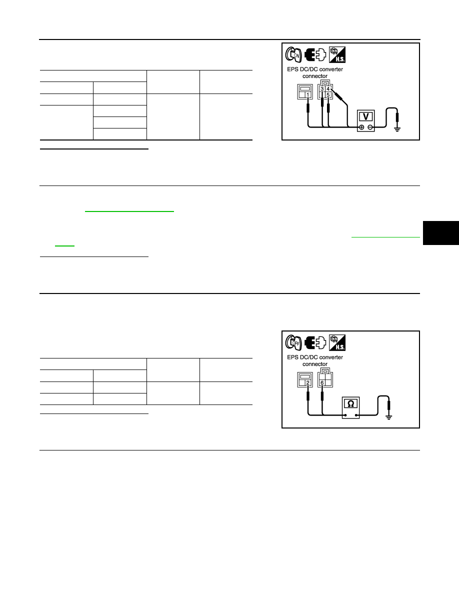
8. Check the voltage between EPS DC/DC converter harness con-

nectors and ground.

Is the inspection result normal?

YES

>> GO TO 4.

NO

>> Repair or replace the harnesses or connectors.

4.

CHECK EPS DC/DC CONVERTER INSTALLATION CONDITION

1. Turn the ignition switch OFF.

2. Check the installation condition of the EPS DC/DC converter ground wire connected to the vehicle body.

Refer to 

STC-60, "Exploded View"

.

CAUTION:

EPS DC/DC converter ground wire is securely installed to the vehicle body.

3. Check the installation condition of the EPS DC/DC converter assembly. Refer to 

STC-60, "Exploded

View"

.

Is the inspection result normal?

YES

>> GO TO 5.

NO

>> Repair each installation condition.

5.

CHECK EPS DC/DC CONVERTER GROUND

1. Turn the ignition switch OFF.

2. Disconnect EPS DC/DC converter harness connectors.

CAUTION:

Turn the ignition switch OFF before disconnecting or reconnecting any harness connector.

3. Check the continuity between EPS DC/DC converter harness

connectors and ground.

Is the inspection result normal?

YES

>> GO TO 6.

NO

>> Repair or replace the harnesses or connectors.

6.

CHECK HV BATTERY CIRCUIT

1. Turn the ignition switch OFF.

2. Disconnect EPS DC/DC converter harness connector and HV battery harness connector.

CAUTION:

Turn the ignition switch OFF before disconnecting or reconnecting any harness connector.

EPS DC/DC converter

Ground

Voltage (Ap-

prox.)

Connector

Terminal

E303

1

Ground

1 V or less

E305

3

4

5

PGIA0097E

EPS DC/DC converter

Ground

Continuity

Connector

Terminal

E304

2

Ground

Existed

E305

6

PGIA0098E

STC-36

< COMPONENT DIAGNOSIS >

C16A1 EPS DC/DC CONVERTER

3. Check the continuity between EPS DC/DC converter harness

connector and HV battery harness connector.

Is the inspection result normal?

YES

>> GO TO 7.

NO

>> Repair or replace the harnesses or connectors.

7.

CHECK EPS DC/DC CONVERTER

Check the EPS DC/DC converter function. Refer to 

STC-36, "Component Inspection"

.

Is the inspection result normal?

YES

>> Replace EPS control unit. Refer to 

STC-58, "Removal and Installation"

.

NO

>> Replace EPS DC/DC converter assembly. Refer to 

STC-60, "Removal and Installation"

.

Component Inspection

INFOID:0000000004212865

1.

CHECK EPS DC/DC CONVERTER

1. Turn the ignition switch OFF.

2. Disconnect EPS control unit harness connector E302.

CAUTION:

Turn the ignition switch OFF before disconnecting or reconnecting any harness connector.

3. Apply 12 V to EPS control unit harness connector E302 terminal 5.

CAUTION:

• Never make the terminals short.

• Connect the 5A fuse between the terminals when applying the voltage.

4. Turn the ignition switch ON (READY).

5. Check the voltage between EPS control unit harness connector

and ground.

CAUTION:

Never make the terminals short.

Is the inspection result normal?

YES

>> INSPECTION END

NO

>> Replace EPS DC/DC converter assembly. Refer to 

STC-60, "Removal and Installation"

.

Special Repair Requirement

INFOID:0000000004212866

1.

INITIALIZE EPS MOTOR ANGLE SENSOR AND CALIBRATE TORQUE SENSOR AGAIN

Always perform EPS motor angle sensor initialization and torque sensor calibration after replacing EPS con-

trol unit or steering gear assembly. Refer to 

STC-5, "EPS MOTOR ANGLE SENSOR INITIALIZATION AND

TORQUE SENSOR CALIBRATION : Special Repair Requirement"

.

>> END

EPS DC/DC converter

HV battery

Continuity

Connector

Terminal

Connector

Terminal

B500

7

B501

26

Existed

8

29

PGIA0099E

EPS control unit

Ground

Voltage (Ap-

prox.)

Connector

Terminal

E302

1

Ground

42 – 45 V

PGIA0112E

C16A2 EPS MOTOR ANGLE SENSOR INITIALIZATION

STC-37

< COMPONENT DIAGNOSIS >

C

D

E

F

H

I

J

K

L

M

A

B

STC

N

O

P

C16A2 EPS MOTOR ANGLE SENSOR INITIALIZATION

Description

INFOID:0000000004212867

This DTC does not indicate a malfunction. The EPS control unit outputs this DTC when it determines that EPS

motor angle sensor value initialization has not been performed. When ignition power is low voltage, EPS

motor angle sensor initialization cannot be performed.

DTC Logic

INFOID:0000000004212868

DTC DETECTION LOGIC

DTC CONFIRMATION PROCEDURE

1.

ERASE DTC MEMORY

 With CONSULT-III

1. Record DTC.

2. Erase DTC once.

NOTE:

After erasing DTC record, currently occurred DTC can be detected by reading out DTC again.

>> GO TO 2.

2.

PERFORM DTC CONFIRMATION

 With CONSULT-III

1. Turn the ignition switch ON (READY).

2. Steer 360

° leftward and rightward slowly.

3. Return the steering wheel to the straight-ahead position.

4. Perform the self-diagnosis.
Is DTC “C16A2” detected?

YES

>> Proceed to 

STC-37, "Diagnosis Procedure"

.

NO

>> INSPECTION END

Diagnosis Procedure

INFOID:0000000004212869

1.

INITIALIZE EPS MOTOR ANGLE SENSOR AND CALIBRATE TORQUE SENSOR

 With CONSULT-III

Perform EPS motor angle sensor initialization and torque sensor calibration. Refer to 

STC-5, "EPS MOTOR

ANGLE SENSOR INITIALIZATION AND TORQUE SENSOR CALIBRATION : Special Repair Requirement"

.

Were they performed correctly?

YES

>> GO TO 2.

NO

>> Check the malfunctioning cause.

2.

PERFORM SELF-DIAGNOSIS AGAIN

 With CONSULT-III

Perform “DTC CONFIRMATION PROCEDURE” (self-diagnosis) again. Refer to 

STC-37, "DTC Logic"

.

Is DTC “C16A2” detected?

YES

>> GO TO 3.

NO

>> INSPECTION END

3.

CHECK THE NUMBER OF WORK SUPPORT IMPLEMENTATIOS

Check the numbers of EPS motor angle sensor initialization and torque sensor calibration.

DTC

Item

(CONSULT-III screen term)

DTC detecting condition

Possible cause

C16A2

ANG SE INT NOT PFM

EPS motor angle sensor initialization is not performed.

• EPS motor angle sen-

sor initialization not 
performed

STC-38

< COMPONENT DIAGNOSIS >

C16A2 EPS MOTOR ANGLE SENSOR INITIALIZATION

How many times were they implemented?

Once/twice>>GO TO 1.

More than twice>>Replace EPS control unit, refer to 

STC-58, "Removal and Installation"

Then GO TO 4.

4.

INITIALIZE EPS MOTOR ANGLE SENSOR AND CALIBRATE TORQUE SENSOR AGAIN

 With CONSULT-III

Perform EPS motor angle sensor initialization and torque sensor calibration again. Refer to 

STC-5, "EPS

MOTOR ANGLE SENSOR INITIALIZATION AND TORQUE SENSOR CALIBRATION : Special Repair

Requirement"

.

Were they performed correctly?

YES

>> GO TO 5.

NO

>> Check the malfunctioning cause.

5.

PERFORM SELF-DIAGNOSIS AGAIN

 With CONSULT-III

Perform “DTC CONFIRMATION PROCEDURE” (self-diagnosis) again. Refer to 

STC-37, "DTC Logic"

.

Is DTC “C16A2” detected?

YES

>> GO TO 6.

NO

>> INSPECTION END

6.

CHECK THE NUMBER OF WORK SUPPORT IMPLEMENTATIOS

Check the numbers of EPS motor angle sensor initialization and torque sensor calibration after replacement of

EPS control unit.
How many times were they implemented?

Once/twice>>GO TO 4.

More than twice>>EPS motor or EPS motor angle sensor is malfunctioning. Replace steering gear assembly.

Refer to 

ST-12, "Removal and Installation"

.

Special Repair Requirement

INFOID:0000000004212870

1.

INITIALIZE EPS MOTOR ANGLE SENSOR AND CALIBRATE TORQUE SENSOR AGAIN

Always perform EPS motor angle sensor initialization and torque sensor calibration after replacing EPS con-

trol unit or steering gear assembly. Refer to 

STC-5, "EPS MOTOR ANGLE SENSOR INITIALIZATION AND

TORQUE SENSOR CALIBRATION : Special Repair Requirement"

.

>> END


Content   ..  1062  1063  1064  1065   ..