Nissan Altima HL32 Hybrid. Manual - part 106


  Index      Nissan     Nissan Altima HL32 Hybrid (2009 year) - Service and Repair Manual


Search            


Content   ..  104  105  106  107   ..


Nissan Altima HL32 Hybrid. Manual - part 106


REAR DISC BRAKE

BR-35

< ON-VEHICLE REPAIR >

C

D

E

G

H

I

J

K

L

M

A

B

BR

N

O

P

• While removing caliper, do not depress brake pedal because the piston will pop out.

• Do not damage piston boot.

• Keep disc rotor free from brake fluid.

• Refill the brake reservoir with new brake fluid “DOT 3”.

• Never reuse drained brake fluid.

REMOVAL

1. Remove rear wheel and tires. Refer to 

WT-62, "Adjustment"

.

2. Fasten disc rotor using a wheel nut.
3. Drain brake fluid. Refer to 

BR-14, "Bleeding Brake System"

.

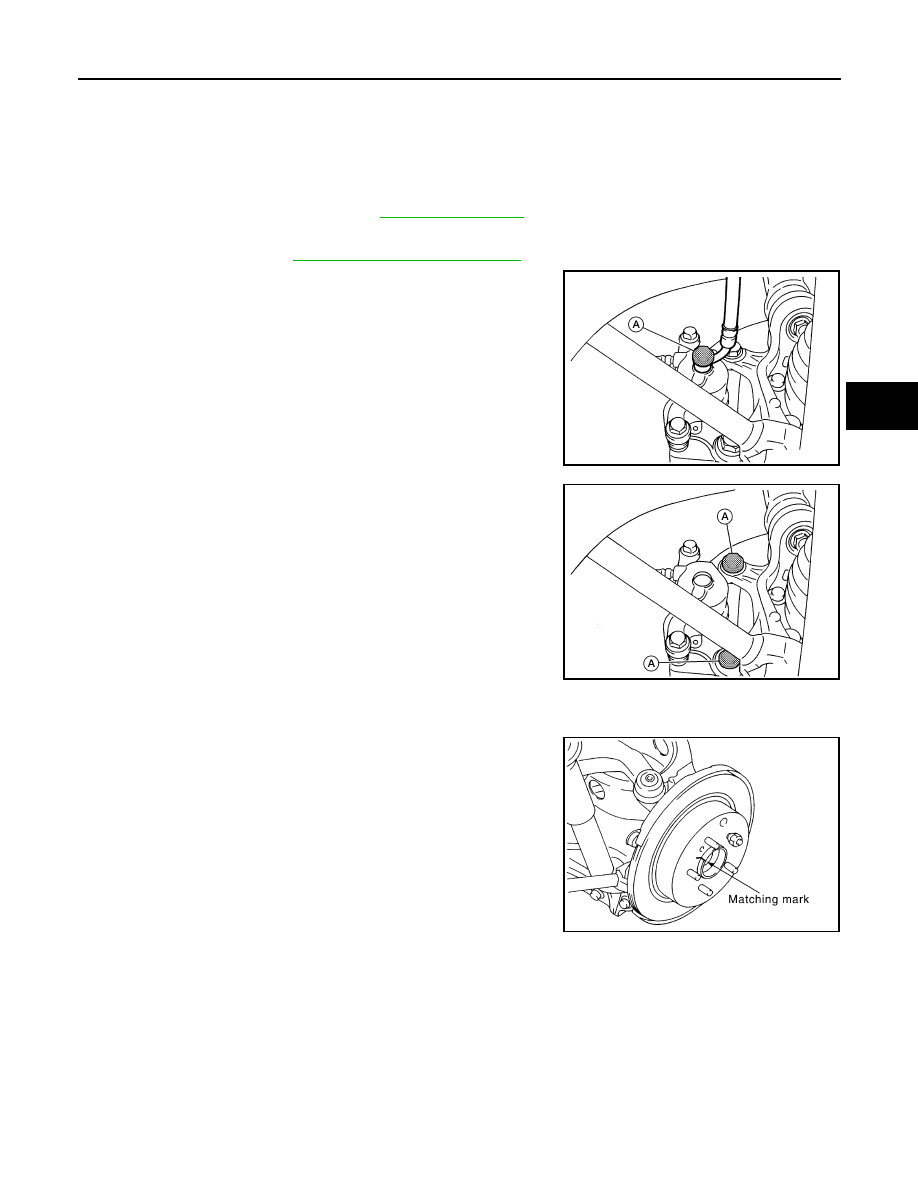
4. Remove union bolt (A) and disconnect the brake hose from the

caliper. Discard the copper washers.

CAUTION:

Do not reuse copper washers.

5. Remove the two torque member bolts (A), and then remove the

torque member, caliper and pads as an assembly.

CAUTION:

Do not drop the brake pad and multilayered shim assem-

blies.

6. Remove the two sliding pin bolts and separate the caliper from the torque member. Remove the brake pad

and multilayered shim assemblies from the caliper.

7. Remove the disc rotor. If reusing the disc rotor, apply matching

marks as shown for installation.

CAUTION:

Put matching marks on wheel hub assembly and disc rotor,

if it necessary to reuse the disc rotor.

INSTALLATION

AWFIA0505ZZ

AWFIA0509ZZ

SDIA2638E

BR-36

< ON-VEHICLE REPAIR >

REAR DISC BRAKE

1. Install the disc rotor. If reusing the disc rotor, align the matching

marks as shown.

CAUTION:

Align the matching marks on the disc rotor and wheel hub

at the time of installation when reusing disc rotor.

2. Install the brake pad and multilayered shim assemblies on the caliper. Refer to 

BR-32, "BRAKE PAD :

Exploded View"

.

3. Install the caliper and pad assembly on the torque member, then tighten the two sliding pin bolts to the

specified torque.

4. Install the torque member, pads and brake caliper assembly,

and tighten the torque member bolts (A) to the specified torque.

CAUTION:

Before installing wipe off all oil and moisture on all mating

surfaces of rear axle and torque member, threads, bolts and

washers.

5. Align the L-shaped pin on the brake hose in the hole in the cali-

per, then install the brake hose with new copper washers and

tighten the union bolt (A) to the specified torque. Refer to 

BR-23,

"REAR BRAKE : Removal and Installation"

.

CAUTION:

Do not reuse copper washers.

6. Refill with new brake fluid and bleed air. Refer to 

BR-14, "Bleeding Brake System"

.

7. Check rear disc brake for drag.
8. Install rear wheel and tires. Refer to 

WT-62, "Adjustment"

.

SDIA2638E

AWFIA0509ZZ

AWFIA0505ZZ

SFIA1137E

BRAKE MASTER CYLINDER

BR-37

< DISASSEMBLY AND ASSEMBLY >

C

D

E

G

H

I

J

K

L

M

A

B

BR

N

O

P

DISASSEMBLY AND ASSEMBLY

BRAKE MASTER CYLINDER

Exploded View

INFOID:0000000004498254

Disassembly and Assembly

INFOID:0000000004498255

CAUTION:

• Do not reuse grommets and gaskets.

• Do not bend or damage the brake tube.

• Do not allow any foreign matter such as dirt and dust to enter the brake line from the connecting

points.

1.

Brake fluid reservoir

2.

Grommet

3.

Master cylinder sub-assembly

4.

Reservoir hose No.1

5.

Reservoir hose No.2

6.

Clamp

7.

Master cylinder sub-assembly

8.

Gasket

9.

Brake simulator 

10. Brake simulator bracket

11. Gasket

12. Clevis

AWFIA0518GB

BR-38

< DISASSEMBLY AND ASSEMBLY >

BRAKE MASTER CYLINDER

• Use a torque wrench with a fulcrum length of 250 mm (9.84 in).

• This torque value is effective when flare nut crowfoot is parallel to a torque wrench.

DISASSEMBLY

Remove screw, brake fluid reservoir and both grommets from master cylinder sub-assembly.

ASSEMBLY

Assembly is in the reverse order of disassembly.


Content   ..  104  105  106  107   ..