Nissan Altima HL32 Hybrid. Manual - part 55


  Index      Nissan     Nissan Altima HL32 Hybrid (2009 year) - Service and Repair Manual


Search            


Content   ..  53  54  55  56   ..


Nissan Altima HL32 Hybrid. Manual - part 55


AV-212

< COMPONENT DIAGNOSIS >

[BOSE AUDIO WITH NAVIGATION]

POWER SUPPLY AND GROUND CIRCUIT

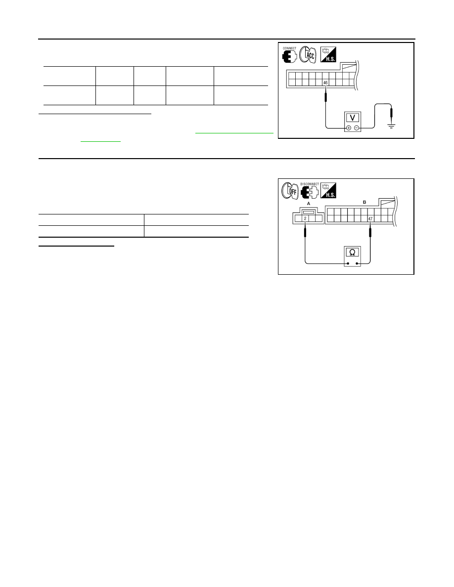
3. Check voltage between AV control unit harness connector and

ground.

Is voltage approximately 5 volts?

YES

>> Inspection End.

NO

>> Replace AV control unit. Refer to 

AV-278, "Removal and

Installation"

.

4.

CHECK GROUND CIRCUIT

1. Turn ignition switch OFF.

2. Disconnect microphone harness connector R7 and AV control unit harness connector M46.

3. Check continuity between microphone harness connector R7

(A) terminal 2 and AV control unit harness connector M46 (B)

terminal 47. 

Does continuity exist?

YES

>> Inspection End.

NO

>> Repair harness or connector.

Signal name

Connector 

No.

Terminal 

No.

Ignition switch 

position

Value (Approx.)

Microphone 

VCC signal

M46

46

ACC

5V

ALLIA0251ZZ

Signal name

Continuity

Ground

Continuity should exist.

ALLIA0252ZZ

AV

FRONT DOOR SPEAKER

AV-213

< COMPONENT DIAGNOSIS >

[BOSE AUDIO WITH NAVIGATION]

C

D

E

F

G

H

I

J

K

L

M

B

A

O

P

FRONT DOOR SPEAKER

Description

INFOID:0000000004219577

The audio unit sends audio signals to the BOSE speaker amp. The BOSE speaker amp. amplifies the audio

signals before sending them to the front door speakers using the audio signal circuits.

Diagnosis Procedure

INFOID:0000000004219578

1.

HARNESS CHECK

1. Disconnect BOSE speaker amp. connector B121 and suspect

speaker connector.

2. Check continuity between BOSE speaker amp. harness connec-

tor B121 (A) and suspect speaker harness connector (B).

3. Check continuity between BOSE speaker amp. harness connec-

tor B121 (A) and ground.

Are continuity test results as specified?

YES

>> GO TO 2

NO

>> • Check connector housings for disconnected or loose terminals.

• Repair harness or connector.

2.

FRONT DOOR SPEAKER SIGNAL CHECK

Terminals

Continuity

A B

Connector

Terminal

Connector

Terminal

B121

58

D3

1

Yes

59

2

71

D103

1

72

2

Terminals

Continuity

A

Connector

Terminal

B121

58

Ground

No

59

71

72

ALNIA0134ZZ

AV-214

< COMPONENT DIAGNOSIS >

[BOSE AUDIO WITH NAVIGATION]

FRONT DOOR SPEAKER

1. Connect BOSE speaker amp. connector B121 and suspect

speaker connector.

2. Turn ignition switch to ACC.

3. Push “POWER” switch.

4. Check the signal between BOSE speaker amp. harness connec-

tor B121 terminals with CONSULT-III or oscilloscope.

Is audio signal voltage as specified?

YES

>> Replace suspect speaker. Refer to 

AV-283, "Removal

and Installation"

.

NO

>> GO TO 3

3.

HARNESS CHECK

1. Disconnect AV control unit connector M47 and BOSE speaker

amp. connector B121.

2. Check continuity between audio unit harness connector M47 (A)

and BOSE speaker amp. harness connector B121 (B).

3. Check continuity between AV control unit harness connector

M47 (A) and ground.

Are continuity test results as specified?

YES

>> GO TO 4

NO

>> • Check connector housings for disconnected or loose terminals.

• Repair harness or connector.

4.

FRONT DOOR SPEAKER SIGNAL CHECK

Connec-

tor

Terminal

Condition

Reference

signal

(+)

(-)

B121

58

59

Receive 
audio sig-
nal

71

72

ALNIA0135ZZ

SKIA0177E

Terminals

Continuity

A

B

Connector

Terminal

Connector

Terminal

M47

2

B121

75

Yes

3

76

11

73

12

74

Terminals

Continuity

A

Connector

Terminal

M47

2

Ground

No

3

11

12

ALNIA0136ZZ

AV

FRONT DOOR SPEAKER

AV-215

< COMPONENT DIAGNOSIS >

[BOSE AUDIO WITH NAVIGATION]

C

D

E

F

G

H

I

J

K

L

M

B

A

O

P

1. Connect AV control unit connector and BOSE speaker amp.

connector.

2. Turn ignition switch to ACC.

3. Push “POWER” switch.

4. Check the signal between AV control unit harness connector ter-

minals with CONSULT-III or oscilloscope.

Are the audio signal voltage readings as specified?

YES

>> Replace BOSE speaker amp. Refer to 

AV-279,

"Removal and Installation"

.

NO

>> Replace AV control unit. Refer to 

AV-278, "Removal and

Installation"

.

Connector

Terminals

Condition

Reference

signal

(+)

(-)

M47

2

3

Receive 
audio sig-
nal

11

12

ALNIA0171ZZ

SKIA0177E


Content   ..  53  54  55  56   ..