Nissan Altima HL32 Hybrid. Manual - part 53


  Index      Nissan     Nissan Altima HL32 Hybrid (2009 year) - Service and Repair Manual


Search            


Content   ..  51  52  53  54   ..


Nissan Altima HL32 Hybrid. Manual - part 53


AV-204

< COMPONENT DIAGNOSIS >

[BOSE AUDIO WITH NAVIGATION]

U1244 GPS ANTENNA

U1244 GPS ANTENNA

Description

INFOID:0000000004219565

Refer to 

AV-150, "System Description"

.

DTC Logic

INFOID:0000000004219566

DTC DETECTION LOGIC

Diagnosis Procedure

INFOID:0000000004219567

1.

GPS ANTENNA CHECK

Inspect GPS antenna and antenna feeder for damage or poor connection.
Is the GPS antenna and feeder clean and undamaged?

YES

>> GO TO 2

NO

>> Repair or replace malfunctioning parts.

2.

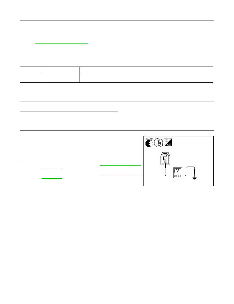
CHECK AV CONTROL UNIT VOLTAGE 

1. Turn ignition switch ON.

2. Check voltage between AV control unit connector M90 terminal

73 and ground.

Is the voltage reading as specified?

YES

>> Replace GPS antenna. Refer to 

AV-290, "Removal and

Installation"

.

NO

>> Replace AV control unit. Refer to 

AV-278, "Removal and

Installation"

.

DTC

CONSULT-III display

Detection condition

U1244

GPS ANTENNA CONN
[U1244]

GPS antenna connection malfunction is detected.

73 - Ground

: Approx. 5V

ALLIA0240ZZ

AV

U124C CD CHANGER

AV-205

< COMPONENT DIAGNOSIS >

[BOSE AUDIO WITH NAVIGATION]

C

D

E

F

G

H

I

J

K

L

M

B

A

O

P

U124C CD CHANGER

Description

INFOID:0000000004219568

Refer to 

AV-150, "System Description"

.

DTC Logic

INFOID:0000000004219569

DTC DETECTION LOGIC

Diagnosis Procedure

INFOID:0000000004219570

1.

CHECK CD CHANGER POWER SUPPLY AND GROUND CIRCUIT

Check CD changer power supply and ground circuit. Refer to 

AV-210, "CD CHANGER : Diagnosis Proce-

dure"

.

Do power and ground check OK?

YES

>> GO TO 2

NO

>> Repair power supply or ground circuit.

2.

CHECK COMMUNICATION CIRCUIT CONTINUITY

1. Turn ignition switch OFF.

2. Disconnect CD changer connector M42 and AV control unit connector M48.

3. Check continuity between CD changer harness connector M42

(A) terminals 8, 9 and 10 and AV control unit harness connector

M48 (B) terminals 69, 70 and 72.

4. Check continuity between CD changer harness connector M42

(A) terminals 8, 9, 10 and ground.

Are the continuity test results as specified?

YES

>> GO TO 3

NO

>> Repair harness or connector.

3.

CHECK REQUEST SIGNAL

1. Connect CD changer connector and AV control unit connector.

2. Turn ignition switch ON.

3. Check signal between CD changer harness connector M42 ter-

minal 8 and ground.

DTC

CONSULT-III display

Detection condition

U124C

N-BUS CD CHG CONN
[U124C]

• A malfunction is detected in CD changer power supply and ground circuits
• Malfunction occurs in request signal circuit. (Between CD changer and AV control unit)
• Malfunction occurs in communication signal circuit. (Between CD changer and AV control 

unit)

8 - 72

: Continuity should exist.

9 - 69

: Continuity should exist.

10 - 70

: Continuity should exist.

8, 9, 10 - Ground

: Continuity should not exist.

ALLIA0236ZZ

8 - Ground

ALLIA0237ZZ

SKIA9299J

AV-206

< COMPONENT DIAGNOSIS >

[BOSE AUDIO WITH NAVIGATION]

U124C CD CHANGER

Are the voltage readings as specified?

YES

>> GO TO 4

NO

>> Replace CD changer. Refer to 

AV-280, "Removal and Installation"

.

4.

CHECK COMMUNICATION SIGNAL

Check signal between CD changer harness connector M42 terminal

9 and ground.

Are the voltage readings as specified?

YES

>> GO TO 5

NO

>> Replace CD changer. Refer to 

AV-280, "Removal and Installation"

.

5.

CHECK COMMUNICATION SIGNAL

Check signal between CD changer harness connector M42 terminal

10 and ground.

Are the voltage readings as specified?

YES

>> Inspection End.

NO

>> Replace AV control unit. Refer to 

AV-278, "Removal and Installation"

.

9 - Ground

ALLIA0238ZZ

SKIA9300J

10 - Ground

ALLIA0239ZZ

SKIA9300J

AV

POWER SUPPLY AND GROUND CIRCUIT

AV-207

< COMPONENT DIAGNOSIS >

[BOSE AUDIO WITH NAVIGATION]

C

D

E

F

G

H

I

J

K

L

M

B

A

O

P

POWER SUPPLY AND GROUND CIRCUIT

AV CONTROL UNIT
AV CONTROL UNIT : Diagnosis Procedure

INFOID:0000000004219571

1.

CHECK FUSE

Check that the following fuses of the AV control unit are not blown.

Are the fuses OK?

YES

>> GO TO 2

NO

>> Be sure to eliminate cause of malfunction before installing new fuse.

2.

CHECK POWER SUPPLY CIRCUIT

Check voltage between AV control unit harness connector and

ground.

Are the voltage tests as specified?

YES

>> GO TO 3

NO

>> Check harness between AV control unit and fuse.

3.

CHECK GROUND CIRCUIT

1. Turn ignition switch OFF.

2. Disconnect AV control unit connectors.

3. Check continuity between AV control unit harness connector

M47 terminal 19 and ground.

Does continuity exist?

YES

>> Inspection End.

NO

>> Repair harness or connector.

REAR VIEW CAMERA CONTROL UNIT
REAR VIEW CAMERA CONTROL UNIT : Diagnosis Procedure

INFOID:0000000004219572

1.

CHECK FUSE

Check that the following fuses of the rear view camera control unit are not blown.

Unit

Terminals

Signal name

Fuse No.

AV control unit

20

Battery power

24

7

Ignition switch ACC or ON

19

10

Ignition switch ON or START

3

Signal name

Connector 

No.

Terminal 

No.

Ignition switch 

position

Value (Ap-

prox.)

Battery power supply

M47

20

OFF

Battery 
voltage

ACC power supply

7

ACC

Ignition signal

10

ON

ALLIA0241ZZ

Signal name

Continuity 

Ground

Continuity should exist.

ALLIA0242ZZ

Unit

Terminals

Signal name

Fuse No.

Rear view camera control unit

1

Battery power

24

2

Ignition switch ACC or ON

19


Content   ..  51  52  53  54   ..