Nissan Frontier. Manual - part 965
LAN-10
< SYSTEM DESCRIPTION >
[CAN FUNDAMENTAL]
TROUBLE DIAGNOSIS
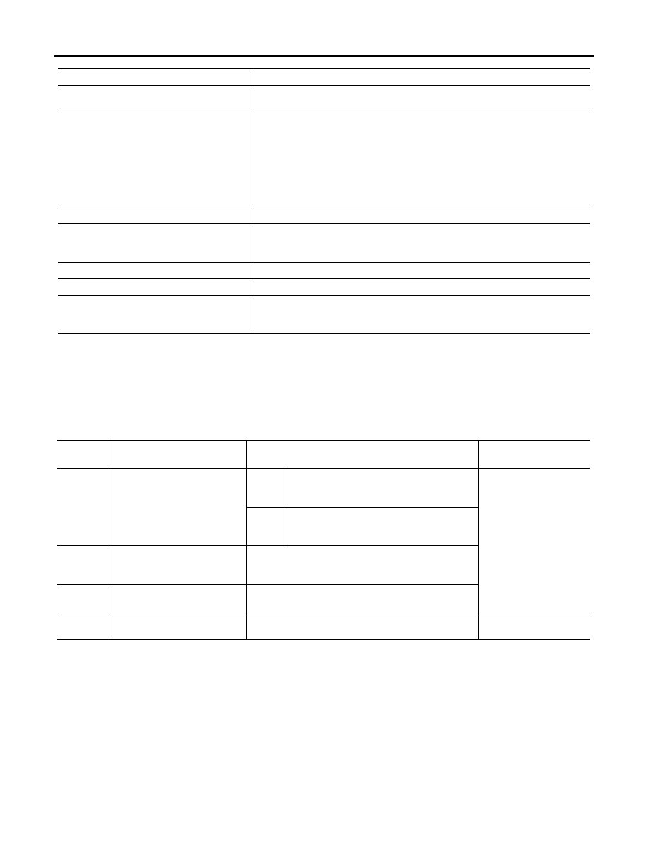
Self-Diagnosis
INFOID:0000000009479090
If communication signals cannot be transmitted or received among units communicating via CAN communica-
tion line, CAN communication-related DTC is displayed on the CONSULT “Self Diagnostic Result” screen.
NOTE:
The following table shows examples of CAN communication-related DTC. For other DTC, refer to the applica-
ble sections.
CAN Diagnostic Support Monitor
INFOID:0000000009479091
CONSULT and CAN diagnostic support monitor (on-board diagnosis function) are used for detecting root
cause.
MONITOR ITEM (CONSULT)
Unit name
Symptom
ECM
• Engine torque limiting is affected, and shift harshness increases.
• Engine speed drops.
BCM
• Reverse warning chime does not sound.
• The front wiper moves under continuous operation mode even though the front
wiper switch being in the intermittent position.
• The room lamp does not turn ON.
• The engine does not start (if an error or malfunction occurs while turning the igni-
tion switch OFF.)
• The steering lock does not release (if an error or malfunction occurs while turning
the ignition switch OFF.)
EPS control unit
The steering effort increases.
Combination meter
• The tachometer and the speedometer do not move.
• Warning lamps turn ON.
• Indicator lamps do not turn ON.
ABS actuator and electric unit (control unit)
Normal operation.
TCM
No impact on operation.
IPDM E/R
When the ignition switch is ON,
• The headlamps (Lo) turn ON.
• The cooling fan continues to rotate.
DTC
Self-diagnosis item
(CONSULT indication)
DTC detection condition
Inspection/Action
U1000
CAN COMM CIRCUIT
ECM
When ECM is not transmitting or receiving
CAN communication signal of OBD (emission-
related diagnosis) for 2 seconds or more.
Start the inspection. Refer
to the applicable section
of the indicated control
unit.
Except
for ECM
When a control unit (except for ECM) is not
transmitting or receiving CAN communication
signal for 2 seconds or more.
U1001
CAN COMM CIRCUIT
When ECM is not transmitting or receiving CAN commu-
nication signal other than OBD (emission-related diagno-
sis) for 2 seconds or more.
U1002
SYSTEM COMM
When a control unit is not transmitting or receiving CAN
communication signal for 2 seconds or less.
U1010
CONTROL UNIT(CAN)
When an error is detected during the initial diagnosis for
CAN controller of each control unit.
Replace the control unit
indicating “U1010”.