Nissan Frontier. Manual - part 893
HAC-126
< DTC/CIRCUIT DIAGNOSIS >
[MANUAL A/C (TYPE 1)]
INTAKE SENSOR
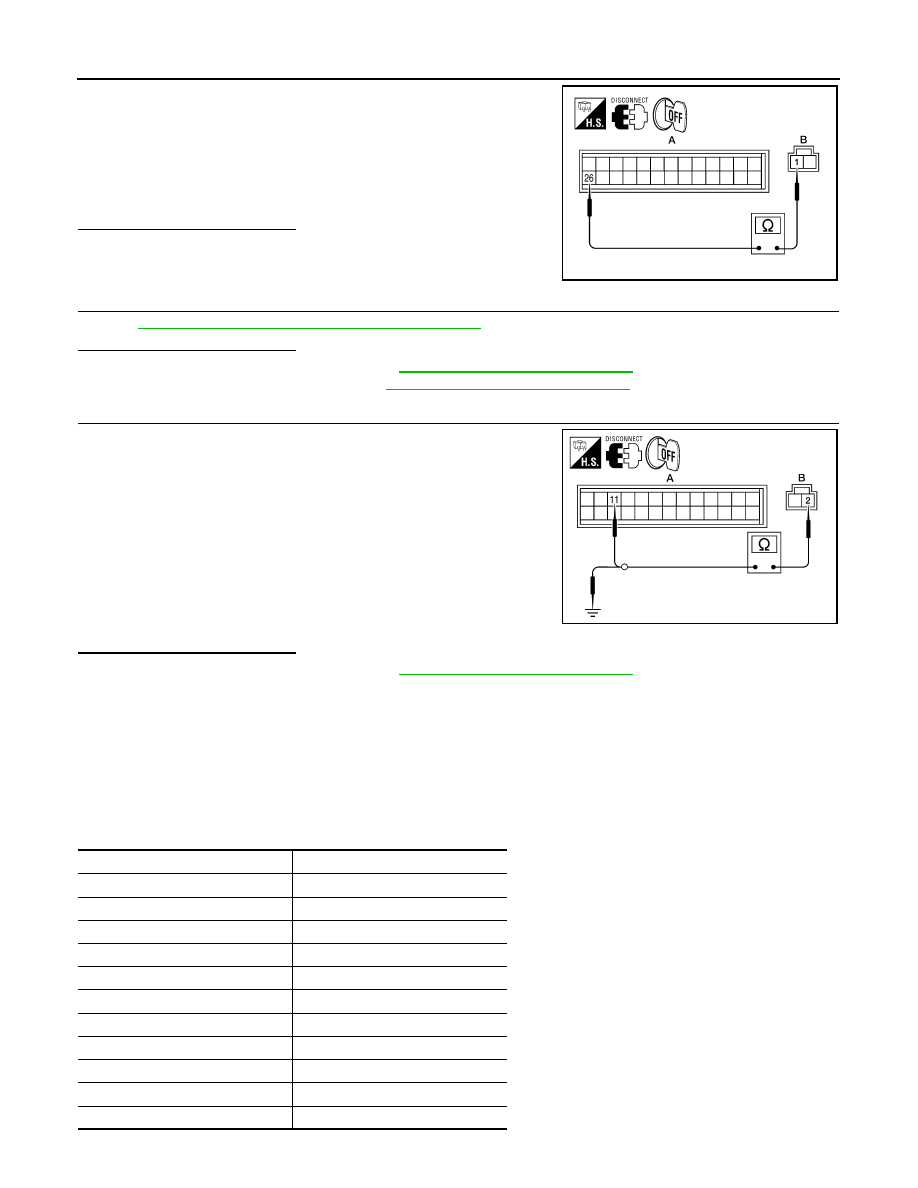
1. Turn ignition switch OFF.
2. Disconnect front air control connector.
3. Check continuity between intake sensor harness connector
M146 (B) terminal 1 and front air control harness connector M50
(A) terminal 26.
Is the inspection result normal?
YES
>> GO TO 3.
NO
>> Repair harness or connector.
3.
CHECK INTAKE SENSOR
HAC-126, "Intake Sensor Component Inspection"
.
Is the inspection result normal?
YES
>> Replace front air control. Refer to
VTL-7, "Removal and Installation"
.
NO
>> Replace intake sensor. Refer to
VTL-10, "Removal and Installation"
4.
CHECK CIRCUIT CONTINUITY BETWEEN INTAKE SENSOR AND FRONT AIR CONTROL
1. Turn ignition switch OFF.
2. Disconnect front air control connector.
3. Check continuity between intake sensor harness connector
M146 (B) terminal 2 and front air control harness connector M50
(A) terminal 11.
4. Check continuity between intake sensor harness connector
M146 (B) terminal 2 and ground.
Is the inspection result normal?
YES
>> Replace front air control. Refer to
VTL-7, "Removal and Installation"
.
NO
>> Repair harness or connector.
Intake Sensor Component Inspection
INFOID:0000000009478353
COMPONENT INSPECTION
Intake Sensor
After disconnecting intake sensor connector, measure resistance between terminals 1 and 2 at sensor har-
ness side, using the table below.
1 - 26
: Continuity should exist.
AWIIA0434ZZ
2 - 11
: Continuity should exist.
2 - Ground
: Continuity should not exist.
AWIIA0435ZZ
Temperature
°C (°F)
Resistance k
Ω
−15 (5)
209.0
−10 (14)
160.0
−5 (23)
123.0
0 (32)
95.8
5 (41)
74.9
10 (50)
58.9
15 (59)
46.7
20 (68)
37.3
25 (77)
30.0
30 (86)
24.2
35 (95)
19.7