Nissan Frontier. Manual - part 865


  Index      Nissan     Nissan Frontier (2014 year) - Service and Repair Manual


Search            


Content   ..  863  864  865  866   ..


Nissan Frontier. Manual - part 865


HAC-14

< SYSTEM DESCRIPTION >

[AUTOMATIC AIR CONDITIONER]

AUTOMATIC AIR CONDITIONER SYSTEM

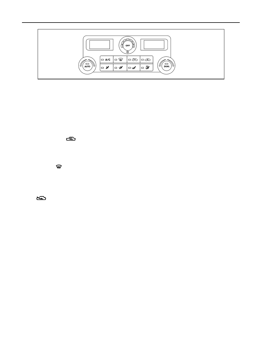
Front air control without rear window defogger

AUTO SWITCH 

• The compressor, intake door, air mix doors, outlet doors and blower speed are automatically controlled so

that the in-vehicle temperature will reach, and be maintained at the set temperature selected by the operator.

• When pressing AUTO switch, air inlet, air outlet, blower speed, and discharge air temperature are automati-

cally controlled.

TEMPERATURE CONTROL DIAL (DRIVER)

Increases or decreases the set temperature.

TEMPERATURE CONTROL DIAL (PASSENGER)

Increases or decreases the set temperature.

RECIRCULATION (

) SWITCH

• When REC switch is ON, REC switch indicator turns ON, and air inlet is set to REC.

• When REC switch is turned OFF, or when compressor is turned from ON to OFF, REC switch is automati-

cally turned OFF. REC mode can be re-entered by pressing REC switch again.

• REC switch is not operated when DEF switch is turned ON, at the D/F position, or in floor position.

DEFROSTER (

) SWITCH

Positions the air outlet doors to the defrost position. Also positions the intake doors to the outside air position,

and turns A/C compressor ON.

REAR WINDOW DEFOGGER SWITCH (IF EQUIPPED)

When switch is ON, rear window and door mirrors are defogged.

FRE (

) SWITCH (IF EQUIPPED)

When FRE switch is ON, FRE switch indicator turns ON, and air inlet is set to FRE.

OFF SWITCH

The compressor and blower are OFF, the intake doors are set to the outside air position, and the air outlet

doors are set to the foot (75% foot and 25% defrost) position.

BLOWER CONTROL DIAL

The blower speed is manually controlled with this dial.

A/C SWITCH

The compressor is ON or OFF.

(Pressing the A/C switch when the AUTO switch is ON will turn off the A/C switch and compressor.)

MODE SWITCHES

Controls the air discharge outlets.

DUAL SWITCH

• When the DUAL switch indicator is illuminated, the driver and passenger temperature can each be set inde-

pendently. 

• When the DUAL switch indicator is not illuminated, the driver temperature setting is applied to both sides.

ALIIA0770ZZ

AUTOMATIC AIR CONDITIONER SYSTEM

HAC-15

< SYSTEM DESCRIPTION >

[AUTOMATIC AIR CONDITIONER]

C

D

E

F

G

H

J

K

L

M

A

B

HAC

N

O

P

MAGNET CLUTCH CONTROL

When A/C switch or DEF switch is pressed, front air control inputs compressor ON signal to BCM.

BCM sends compressor ON signal to ECM and front air control, via CAN communication line.

ECM judges whether compressor can be turned ON, based on each sensor status (refrigerant pressure sen-

sor signal, throttle angle sensor, etc.). If it judges compressor can be turned ON, it sends compressor ON sig-

nal to IPDM E/R, via CAN communication line.

Upon receipt of compressor ON signal from ECM, IPDM E/R turns air conditioner relay ON to operate com-

pressor.

Discharge Air Flow

INFOID:0000000009478267

WJIA2197E

Mode door position

Air outlet/distribution

Vent

Foot

Defroster

95%

5%

60%

40%

70%

30%

60%

40%

10%

90%

WJIA0540E

HAC-16

< SYSTEM DESCRIPTION >

[AUTOMATIC AIR CONDITIONER]

AUTOMATIC AIR CONDITIONER SYSTEM

Switches And Their Control Function

INFOID:0000000009478268

*1

: Inlet status is displayed by indicator when activating D/F mode.

*2

: If equipped (without rear defogger).

ALIIA0755GB

Switch/Dial position

Door position

Ventilator

door

MAX-COOL

door

Defroster

door

Intake

door

Air mix

door

MODE 

switch

VENT

A

A

D

B/L

B

B

D

FOOT

C

B

D or C

D/F

C

B

B

DEF switch

C

C

A

B

REC switch

*1

A

FRE switch

*2

B

Temperature control dial

Full Cold

A

Full Cold 

⇔ Full Hot

AUTO

Full Hot

B

DIAGNOSIS SYSTEM (HVAC)

HAC-17

< SYSTEM DESCRIPTION >

[AUTOMATIC AIR CONDITIONER]

C

D

E

F

G

H

J

K

L

M

A

B

HAC

N

O

P

DIAGNOSIS SYSTEM (HVAC)

CONSULT Function (HVAC)

INFOID:0000000009478269

CONSULT can display each diagnostic item using the diagnostic test modes shown following.

SELF-DIAGNOSIS

Display Item List

DATA MONITOR

Display Item List

Diagnostic mode

Description

SELF DIAGNOSTIC RESULT 

Displays Front air control self-diagnosis results.

DATA MONITOR

Displays Front air control input/output data in real time.

CAN DIAG SUPPORT MNTR

The result of transmit/receive diagnosis of CAN communication can be read.

ECU IDENTIFICATION

Front air control part number can be read.

DTC

Description

Reference page

B2573

Battery voltage out of range

CHG-2, "Work Flow (With EXP-800 NI or GR8-1200 NI)"

 or 

CHG-5, "Work Flow (Without EXP-800 NI or GR8-1200 NI)"

B2578

In-vehicle sensor circuit out of range (low)

HAC-51, "In-Vehicle Sensor Diagnosis Procedure"

B2579

In-vehicle sensor circuit out of range (high)

B257B

Ambient sensor circuit short

HAC-49, "Ambient Sensor Component Inspection"

B257C

Ambient sensor circuit open

B257F

Optical sensor (Driver) circuit open or short

HAC-54, "Optical Sensor Diagnosis Procedure"

.

B2580

Optical sensor (Passenger) circuit open or short

B2581

Intake sensor circuit short

HAC-57, "Intake Sensor Component Inspection"

B2582

Intake sensor circuit open

B2587

Stuck button

VTL-7, "Removal and Installation"

U1000

CAN bus fault

LAN-14, "Trouble Diagnosis Flow Chart"

Monitor item

Value

Contents

BATT VIA CAN

"V"

Displays battery voltage signal.

IGN VIA CAN 

"ON/OFF"

Displays ignition switch signal.

DVR SUNLD SEN

"w/m2"

Displays optical sensor (driver) signal.

PAS SUNLD SEN

"w/m2"

Displays optical sensor (passenger) signal.

AMB TEMP SEN

"

°C"

Displays ambient sensor signal.

EVAP TEMP SEN

"

°C"

Displays intake sensor signal.

INCAR TMP SEN

"

°C"

Displays in-vehicle sensor signal.

RR TEMPSET FR

"V"

Displays air mix door (front) set point signal.

RR TEMPSET RR

"V"

Displays air mix door (rear) set point signal.

MODE FDBCK

"V"

Displays mode door motor feedback signal.

DVR MIX FDBCK

"V"

Displays air mix door motor (driver) feedback signal.

PAS MIX FDBCK

"V"

Displays air mix door motor (passenger) feedback signal.

RR FDBCK

"V"

Displays air mix door motor (rear) feedback signal.


Content   ..  863  864  865  866   ..