Nissan Frontier. Manual - part 861
HA-36
< REMOVAL AND INSTALLATION >
REFRIGERANT PRESSURE SENSOR
REFRIGERANT PRESSURE SENSOR
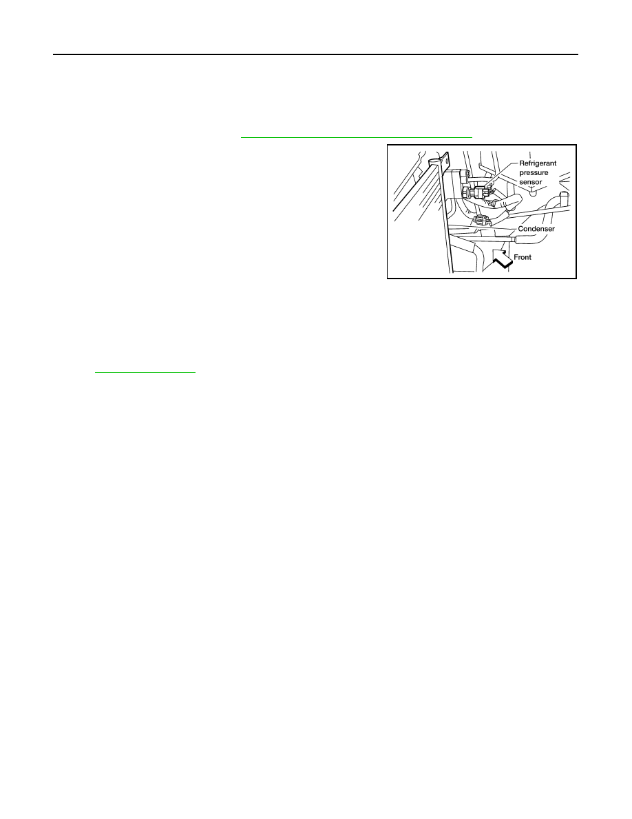
Removal and Installation
INFOID:0000000009478597
REMOVAL
1. Discharge the refrigerant. Refer to
HA-14, "HFC-134a (R-134a) Service Procedure"
.
2. Disconnect the harness connector from the refrigerant pressure
sensor.
3. Remove the refrigerant pressure sensor from the condenser.
CAUTION:
Be careful not to damage the condenser fins.
INSTALLATION
Installation is in the reverse order of removal.
CAUTION:
• Be careful not to damage the condenser fins.
• Do not reuse O-rings.
• Apply A/C oil to the O-ring of the refrigerant pressure sensor for installation.
• After charging refrigerant, check for leaks.
LJIA0177E