Nissan Frontier. Manual - part 859


  Index      Nissan     Nissan Frontier (2014 year) - Service and Repair Manual


Search            


Content   ..  857  858  859  860   ..


Nissan Frontier. Manual - part 859


HA-28

< REMOVAL AND INSTALLATION >

COMPRESSOR

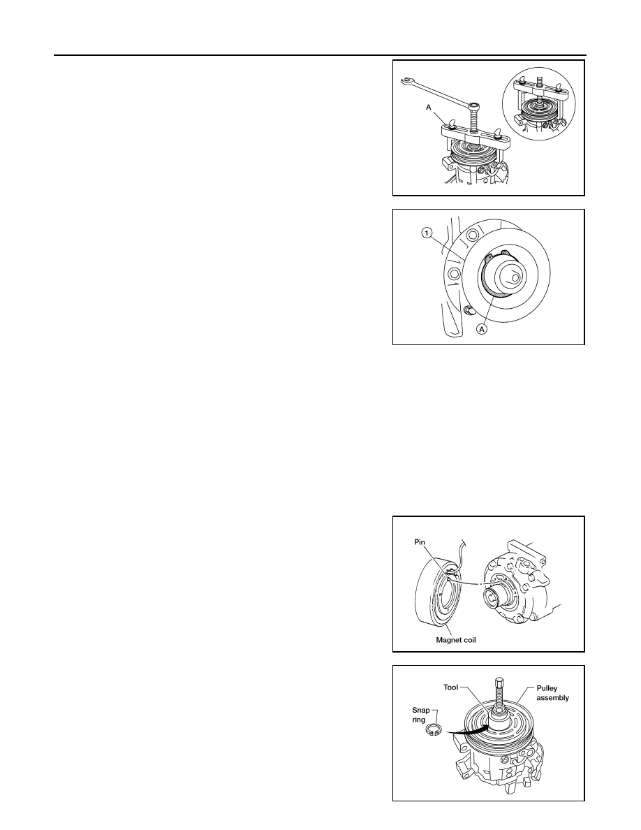
6. Remove the pulley using Tool (A) (QR25DE), or suitable tool (A)

(VQ40DE).

CAUTION:

To prevent deformation of the pulley groove, the puller

claws should be hooked under the pulley groove and not

into the pulley groove.

7. Remove the magnet coil snap ring (A) using a suitable tool and

remove the magnet coil (1).

INSPECTION

Clutch Disc

If the contact surface shows signs of damage due to excessive heat, replace clutch disc and pulley.

Pulley

Check the appearance of the pulley assembly. If contact surface of pulley shows signs of excessive grooving,

replace clutch disc and pulley. The contact surfaces of the pulley assembly should be cleaned with a suitable

solvent before reinstallation.

Coil

Check magnet coil for loose connections or any cracked insulation. Replace as necessary.

INSTALLATION

1. Install the magnet coil and snap ring using a suitable tool.

CAUTION:

Be sure to align the magnet coil pin with the hole in the

compressor front head.

2. Install the pulley assembly using Tool and a wrench, then install

the snap ring using a suitable tool.

Tool number
(QR25DE only)

: KV99233130 (J-29884)

AWIIA1285ZZ

ALIIA0379ZZ

WHA213

Tool number

: — (J-38873-A)

WJIA1016E

COMPRESSOR

HA-29

< REMOVAL AND INSTALLATION >

C

D

E

F

G

H

J

K

L

M

A

B

HA

N

O

P

3. Install the clutch disc on the compressor shaft, together with all

of the original shim(s) using a suitable tool. Press the clutch disc

in by hand.

4. Install the clutch pulley bolt while using Tool to prevent the clutch

disc from turning and tighten the bolt to specification.

CAUTION:

After tightening the clutch pulley bolt, check that the clutch

pulley rotates smoothly.

5. Check the pulley clearance all the way around the clutch disc as

shown.

6. If the specified clearance is not obtained, replace the adjusting

spacer to readjust.

7. Install the cooling fan. Refer to 

CO-19, "Removal and Installa-

tion (Crankshaft driven type)"

 (QR25DE), 

CO-47, "Removal and

Installation (Crankshaft driven type)"

 (VQ40DE).

8. Install the engine room cover (VQ40DE only). Refer to 

EM-140,

"Removal and Installation"

.

BREAK-IN OPERATION

When replacing compressor clutch assembly, always conduct the break-in operation. This is done by engag-

ing and disengaging the clutch about 30 times. Break-in operation raises the level of transmitted torque.

WHA184

Tool number

:  — (J-44614)

WHA229

Clutch disc-to-pulley clearance

: 0.3 - 0.6 mm 
(0.012 - 0.024 in)

WHA194

HA-30

< REMOVAL AND INSTALLATION >

HIGH-PRESSURE FLEXIBLE HOSE

HIGH-PRESSURE FLEXIBLE HOSE

Removal and Installation

INFOID:0000000009478591

REMOVAL

1. Remove the front left wheel and tire. Refer to 

WT-48, "Adjustment"

.

2. Remove the front left mudguard. Refer to 

EXT-29, "Removal and Installation"

.

3. Remove the front left fender protector. Refer to 

EXT-27, "Removal and Installation of Front Fender Protec-

tor"

.

4. Discharge the refrigerant. Refer to 

HA-14, "HFC-134a (R-134a) Service Procedure"

.

5. Remove the high-pressure flexible A/C hose.

CAUTION:

Cap or wrap the joint of the pipe with suitable material such as vinyl tape to avoid the entry of air. 

INSTALLATION

Installation is in the reverse order of removal.

Refer to 

HA-23, "Component"

.

CAUTION:

• Do not reuse O-rings.

• Apply A/C oil to the O-ring of the high-pressure flexible A/C hose for installation.

• After charging refrigerant, check for leaks.

HIGH-PRESSURE PIPE

HA-31

< REMOVAL AND INSTALLATION >

C

D

E

F

G

H

J

K

L

M

A

B

HA

N

O

P

HIGH-PRESSURE PIPE

Removal and Installation

INFOID:0000000009478592

REMOVAL

1. Remove the front right wheel and tire (VQ40DE only). Refer to 

WT-48, "Adjustment"

.

2. Remove the front right mudguard (VQ40DE only). Refer to 

EXT-29, "Removal and Installation"

.

3. Remove the front right fender protector (VQ40DE only). Refer to 

EXT-27, "Removal and Installation of

Front Fender Protector"

.

4. Discharge the refrigerant. Refer to 

HA-14, "HFC-134a (R-134a) Service Procedure"

.

5. Remove the low pressure A/C pipe. Refer to 

HA-33, "Removal and Installation"

.

6. Remove the high-pressure A/C pipe.

CAUTION:

Cap or wrap the joint of the pipe with suitable material such as vinyl tape to avoid the entry of air. 

INSTALLATION

Installation is in the reverse order of removal.

Refer to 

HA-23, "Component"

.

CAUTION:

• Do not reuse O-rings.

• Apply A/C oil to the O-ring of the high-pressure A/C pipe for installation.

• After charging refrigerant, check for leaks.


Content   ..  857  858  859  860   ..