Nissan Frontier. Manual - part 856
 

  Index      Nissan     Nissan Frontier (2014 year) - Service and Repair Manual


Search            


Content   ..  854  855  856  857   ..


Nissan Frontier. Manual - part 856


HA-16

< PERIODIC MAINTENANCE >

OIL

OIL

Maintenance of Oil Quantity in Compressor

INFOID:0000000009478581

The oil in the compressor circulates through the system with the refrigerant. Add oil to compressor when

replacing any component or after a large refrigerant leakage has occurred. It is important to maintain the spec-

ified amount.

If oil quantity is not maintained properly, the following malfunctions may result:

• Lack of oil: May lead to a seized compressor

• Excessive oil: Inadequate cooling (thermal exchange interference)

OIL

Name: NISSAN A/C System Oil Type R or equivalent

CHECKING AND ADJUSTING

CAUTION:

• The use of any other refrigerant or oil will cause severe damage to the air conditioning system and

will require the replacement of all air conditioner system components.

• If excessive oil leakage is noted, do not perform the oil return operation.

Start the engine and set the following conditions:

Test Condition

• Engine speed: Idling to 1,200 rpm

• A/C switch: On

• Blower fan speed: Max. position

• Temp. control: Optional [Set so that intake air temperature is 25

° to 30° C (77° to 86°F)]

• Intake position: Recirculation (

)

• Perform oil return operation for about ten minutes

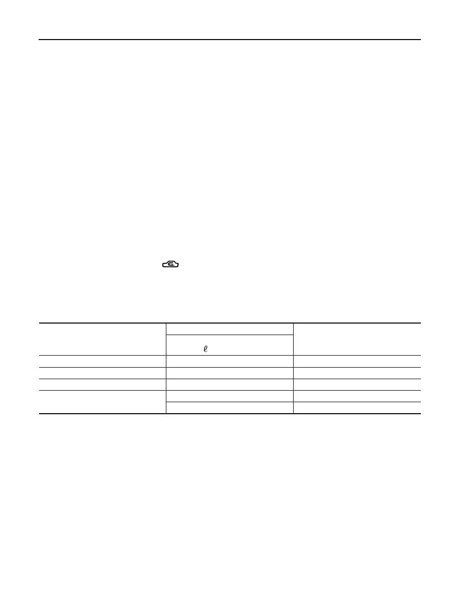
Adjust the oil quantity according to the following table.

Oil Adjusting Procedure for Components Replacement Except Compressor

After replacing any of the following major components, add the correct amount of oil to the system.

Amount of Oil to be Added

*1: If refrigerant leak is small, no addition of oil is needed.

Oil Adjustment Procedure for Compressor Replacement

Part replaced

Oil to be added to system

Remarks

Amount of oil

m  (US fl oz, Imp fl oz)

Evaporator

75 (2.5, 2.6)

Condenser

75 (2.5, 2.6)

Liquid tank

5 (0.2, 0.2)

Add if compressor is not replaced.

In case of refrigerant leak

30 (1.0, 1.1)

Large leak

Small leak *1

OIL

HA-17

< PERIODIC MAINTENANCE >

C

D

E

F

G

H

J

K

L

M

A

B

HA

N

O

P

1. Before connecting recovery/recycling equipment to vehicle, check recovery/recycling equipment gauges.

No refrigerant pressure should be displayed. If NG, recover refrigerant from equipment lines.

2. Connect recovery/recycling equipment to vehicle. Confirm refrigerant purity in supply tank using recovery/

recycling equipment and refrigerant identifier. If NG, refer to 

HA-3, "Contaminated Refrigerant"

.

3. Confirm refrigerant purity in vehicle A/C system using recovery/recycling equipment and refrigerant identi-

fier. If NG, refer to 

HA-3, "Contaminated Refrigerant"

.

4. Discharge refrigerant into the refrigerant recovery/recycling equipment. Measure oil discharged into the

recovery/recycling equipment.

5. Drain the oil from the “old” (removed) compressor into a graduated container and recover the amount of

oil drained.

6. Drain the oil from the “new” compressor into a separate, clean container.
7. Measure an amount of new oil installed equal to amount drained from “old” compressor. Add this oil to

“new” compressor through the suction port opening.

8. Measure an amount of new oil equal to the amount recovered during discharging. Add this oil to “new”

compressor through the suction port opening.

9. If the liquid tank also needs to be replaced, add an additional 5 m  (0.2 US fl oz, 0.2 Imp fl oz) of oil at this

time.
Do not add this 5 m  (0.2 US fl oz, 0.2 Imp fl oz) of oil if only replacing the compressor.

1.

New compressor

2.

Old compressor

3.

Recovery/recycling equipment

4.

Measuring cup X

5.

Measuring cup Y

6.

New oil

A.

Drain oil from the new compressor 
into clean container

B.

Record amount of oil recovered

C.

Add an additional 5 m  (0.2 US fl oz, 
0.2 Imp fl oz) of new oil when replacing 
liquid tank

D.

Install new oil equal to recorded 
amounts in measuring cups X plus Y 

WJIA1716E

HA-18

< PERIODIC MAINTENANCE >

FLUORESCENT LEAK DETECTOR

FLUORESCENT LEAK DETECTOR

Checking of Refrigerant Leaks

INFOID:0000000009478582

Perform a visual inspection of all refrigeration parts, fittings, hoses and components for signs of A/C oil leak-

age, damage, and corrosion. Any A/C oil leakage may indicate an area of refrigerant leakage. Allow extra

inspection time in these areas when using either an electronic refrigerant leak detector (J-41995) or fluores-

cent dye leak detector (J-42220).

If any dye is observed using a fluorescent dye leak detector (J-42220), confirm the leak using a electronic

refrigerant leak detector (J-41995). It is possible that the dye is from a prior leak that was repaired and not

properly cleaned.

When searching for leaks, do not stop when one leak is found but continue to check for additional leaks at all

system components and connections.

When searching for refrigerant leaks using an electronic refrigerant leak detector (J-41995), move the probe

along the suspected leak area at 25 - 50 mm (1 - 2 in) per second and no further than 6 mm (1/4 in) from the

component.

CAUTION:

Moving the electronic refrigerant leak detector probe slower and closer to the suspected leak area will

improve the chances of finding a leak.

Checking System for Leaks Using the Fluorescent Dye Leak Detector

INFOID:0000000009478583

1. Check the A/C system for leaks using the fluorescent dye leak detector and safety goggles (J-42220) in a

low sunlight area (area without windows preferable). Illuminate all components, fittings and lines. The dye

will appear as a bright green/yellow area at the point of leakage. Fluorescent dye observed at the evapo-

rator drain opening indicates an evaporator core assembly leak (tubes, core or expansion valve).

2. If the suspected area is difficult to see, use an adjustable mirror or wipe the area with a clean shop rag or

cloth, then inspect the shop rag or cloth with the fluorescent dye leak detector (J-42220) for dye residue.

3. After the leak is repaired, remove any residual dye using refrigerant dye cleaner (J-43872) to prevent

future misdiagnosis.

4. Perform a system performance check and then verify the leak repair using a electronic refrigerant leak

detector (J-41995).

NOTE:

• Other gases in the work area or substances on the A/C components, for example, anti-freeze, wind-

shield washer fluid, solvents and oils, may falsely trigger the leak detector. Make sure the surfaces to be

checked are clean.

• Clean with a dry cloth or blow off with shop air.

• Do not allow the sensor tip of the electronic refrigerant leak detector (J-41995) to contact with any sub-

stance. This can also cause false readings and may damage the detector.

Dye Injection

INFOID:0000000009478584

NOTE:

This procedure is only necessary when recharging the system or when the compressor has seized and must

be replaced.
1. Check the A/C system static (at rest) pressure. Pressure must be at least 345 kPa (3.52 kg/cm

2

, 50 psi).

2. Pour one bottle 7.4 cc (1/4 ounce) of the HFC-134a (R-134a) fluorescent leak detection dye (J-41447) into

the HFC-134a (R-134a) refrigerant dye injector (J-41459).

CAUTION:

If repairing the A/C system or replacing a component, pour the HFC-134a (R-134a) fluorescent leak

detection dye (J-41447) directly into the open system connection and proceed with the service

procedures.

3. Connect the refrigerant dye injector (J-41459) to the low-pressure service valve.
4. Start the engine and switch the A/C system ON.
5. When the A/C system is operating (compressor running), inject one bottle 7.4 cc (1/4 ounce) of HFC-134a

(R-134a) fluorescent leak detection dye (J-41447) through the low-pressure service valve using HFC-

134a (R-134a) refrigerant dye injector (J-41459). Refer to the manufacturer's operating instructions.

6. With the engine still running, disconnect the HFC-134a (R-134a) refrigerant dye injector (J-41459) from

the low-pressure service valve.

FLUORESCENT LEAK DETECTOR

HA-19

< PERIODIC MAINTENANCE >

C

D

E

F

G

H

J

K

L

M

A

B

HA

N

O

P

7. Operate the A/C system for a minimum of 20 minutes to mix the HFC-134a (R-134a) fluorescent leak

detection dye (J-41447) with the A/C system oil. Depending on the leak size, operating conditions and

location of the leak, it may take from minutes to days for the HFC-134a (R-134a) fluorescent leak detec-

tion dye to penetrate an A/C system leak and become visible.


Content   ..  854  855  856  857   ..