Nissan Frontier. Manual - part 855


  Index      Nissan     Nissan Frontier (2014 year) - Service and Repair Manual


Search            


Content   ..  853  854  855  856   ..


Nissan Frontier. Manual - part 855


HA-12

< PREPARATION >

PREPARATION

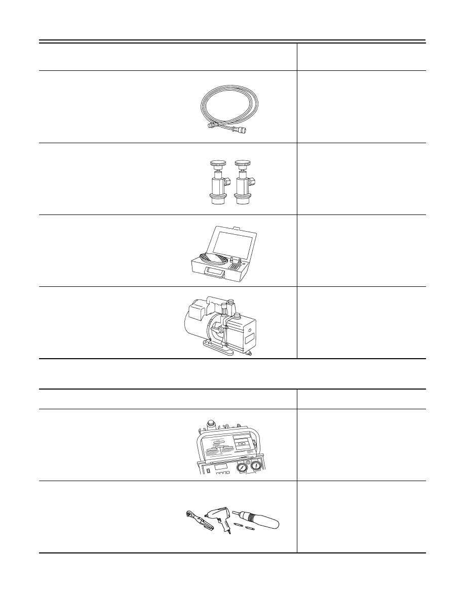
Commercial Service Tool

INFOID:0000000009478577

Service hoses:
• High side hose

(J-39500-72B)

• Low side hose

(J-39500-72R)

• Utility hose

(J-39500-72Y)

Hose color:
• Low side hose: Blue with black stripe
• High side hose: Red with black stripe
• Utility hose: Yellow with black stripe or 

green with black stripe
Hose fitting to gauge:

• 1/2”-16 ACME

Service couplers
• High side coupler

(J-39500-20A)

• Low side coupler

(J-39500-24A)

Hose fitting to service hose:
• M14 x 1.5 fitting is optional or perma-

nently attached.

(J-39699)
Refrigerant weight scale

For measuring of refrigerant
Fitting size-Thread size
• 1/2”-16 ACME

(J-39649)
Vacuum pump
(Including the isolator valve)

Capacity:
• Air displacement: 4 CFM
• Micron rating: 20 microns
• Oil capacity: 482 g (17 oz)

Fitting size-Thread size

• 1/2”-16 ACME

Tool number
(TechMate No.)
Tool name

Description 

S-NT201

S-NT202

S-NT200

S-NT203

(TechMate No.)
Tool name

Description

(J-41810-NI)
Refrigerant identifier equipment (R-
134a)

For checking refrigerant purity and sys-
tem contamination

Power tool

Loosening nuts, screws and bolts

RJIA0197E

PIIB1407E

REFRIGERATION SYSTEM

HA-13

< SYSTEM DESCRIPTION >

C

D

E

F

G

H

J

K

L

M

A

B

HA

N

O

P

SYSTEM DESCRIPTION

REFRIGERATION SYSTEM

Refrigerant Cycle

INFOID:0000000009478578

REFRIGERANT FLOW

The refrigerant flows in the standard pattern. Refrigerant flows through the compressor, condenser, liquid tank,

expansion valve, evaporator, and back to the compressor. The refrigerant evaporation through the evaporator

coil is controlled by an externally equalized expansion valve, located inside the evaporator case.

FREEZE PROTECTION

The compressor cycles on and off to maintain the evaporator temperature within a specified range. When the

evaporator coil temperature falls below a specified point, the intake sensor interrupts the compressor opera-

tion. When the evaporator coil temperature rises above the specification, the intake sensor allows compressor

operation.

Refrigerant System Protection

INFOID:0000000009478579

REFRIGERANT PRESSURE SENSOR

The refrigerant system is protected against excessively high- or low-pressures by the refrigerant pressure sen-

sor, located on the condenser. If the system pressure rises above or falls below the specifications, the refriger-

ant pressure sensor detects the pressure inside the refrigerant line and sends a voltage signal to the ECM.

The ECM de-energizes the A/C relay to disengage the magnetic compressor clutch when pressure on the high
pressure side detected by refrigerant pressure sensor is over about 2,746 kPa (28 kg/cm

2

, 398 psi), or below

about 120 kPa (1.22 kg/cm

2

, 17.4 psi).

PRESSURE RELIEF VALVE

The refrigerant system is also protected by a pressure relief valve, located in the rear head of the compressor.

When the pressure of refrigerant in the system increases to an abnormal level [more than 2,990 kPa (30.5 kg/
cm

2

, 433.6 psi)], the release port on the pressure relief valve automatically opens and releases refrigerant into

the atmosphere.

WJIA1482E

HA-14

< PERIODIC MAINTENANCE >

REFRIGERATION SYSTEM

PERIODIC MAINTENANCE

REFRIGERATION SYSTEM

HFC-134a (R-134a) Service Procedure

INFOID:0000000009478580

SETTING OF SERVICE TOOLS AND EQUIPMENT

Discharging Refrigerant

WARNING:

Avoid breathing A/C refrigerant and oil vapor or mist. Exposure may irritate eyes, nose and throat.

Remove HFC-134a (R-134a) refrigerant from the A/C system using certified service equipment meeting

requirements of SAE J2210 HFC-134a (R-134a) recycling equipment or SAE J2201 HFC-134a (R-134a)

recovery equipment. If an accidental system discharge occurs, ventilate the work area before resum-

ing service. Additional health and safety information may be obtained from the refrigerant and oil man-

ufacturers.

Evacuating System and Charging Refrigerant

1.

Shut-off valve

2.

A/C service valve

3.

Recovery/Recycling equipment

WJIA1160E

WJIA1161E

REFRIGERATION SYSTEM

HA-15

< PERIODIC MAINTENANCE >

C

D

E

F

G

H

J

K

L

M

A

B

HA

N

O

P

1.

Shut-off valve

2.

A/C service valve

3.

Recovery/Recycling equipment

4.

Refrigerant container (HFC-134a)

5.

Refrigerant weight scale

6.

Vacuum pump

7.

Manifold gauge set with hoses and 
couplers

*1  

HA-14, "HFC-134a (R-134a) Service 

Procedure"

*3

HA-18, "Checking of Refrigerant 
Leaks"

*5

HA-3, "Contaminated Refrigerant"

*2

HA-18, "Checking of Refrigerant 
Leaks"

*4

HAC-90, "Operational Check"

WJIA1923E


Content   ..  853  854  855  856   ..