Nissan Frontier. Manual - part 760


  Index      Nissan     Nissan Frontier (2014 year) - Service and Repair Manual


Search            


Content   ..  758  759  760  761   ..


Nissan Frontier. Manual - part 760


ENGINE UNIT

EM-229

< UNIT DISASSEMBLY AND ASSEMBLY >

[VQ40DE]

C

D

E

F

G

H

I

J

K

L

M

A

EM

N

P

O

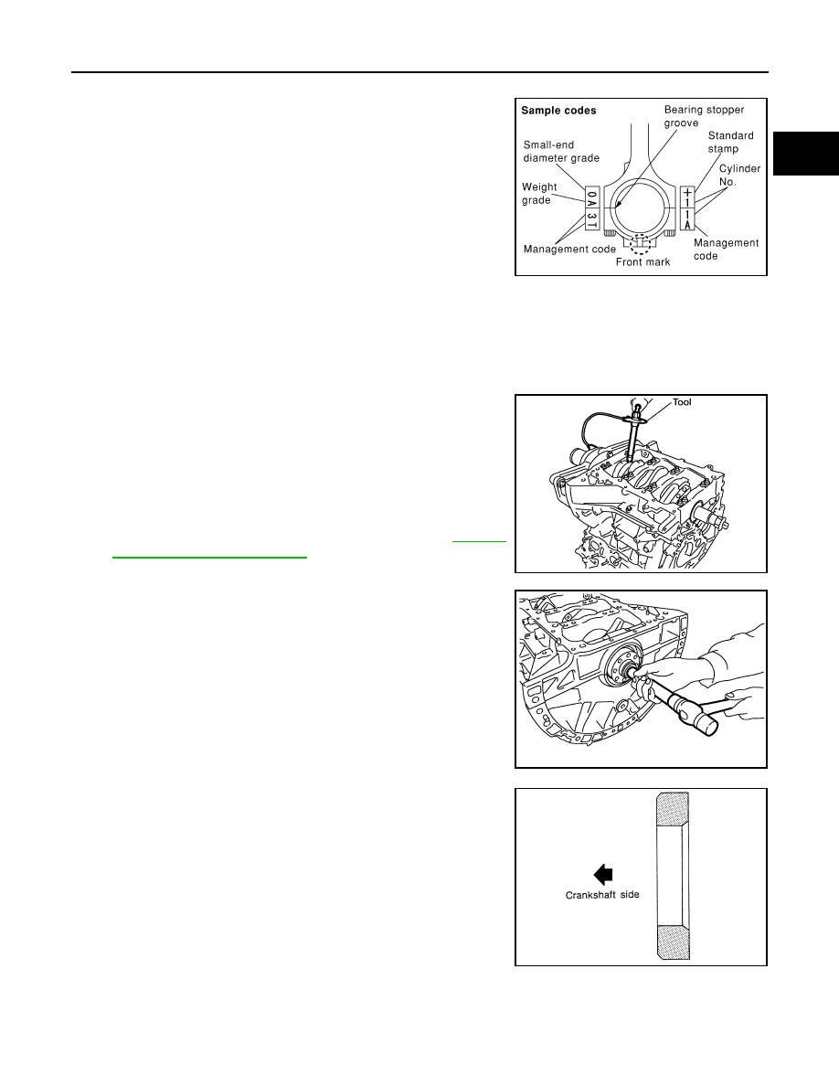
17. Install connecting rod bearing cap.

• Match the stamped cylinder number marks on connecting rod

with those on connecting rod bearing cap to install.

• Be sure that front mark on connecting rod bearing cap is fac-

ing front of engine.

18. Tighten connecting rod bolts as follows:
a. Apply engine oil to the threads and seats of connecting rod bolts. 
b. Tighten connecting rod bolts.

c. Then tighten all connecting rod bolts 90

° clockwise.

CAUTION:

Always use Tool. Avoid tightening based on visual check

alone.

• After tightening connecting rod bolts, make sure that crank-

shaft rotates smoothly.

• Check the connecting rod side clearance. Refer to 

EM-230,

"Inspection After Disassembly"

.

19. Install pilot converter.

• With drift of the following outer diameter, press-fit as far as it

will go.

• Press-fit pilot converter with its chamfer facing crankshaft as

shown. 

20. Install knock sensors.

CAUTION:

• Do not tighten bolts while holding connector.   

• If knock sensor is dropped, replace it with new one.

PBIC0809E

Connecting rod bolt  : 19.6 N·m (2.0 kg-m, 14 ft-lb)

Tool number

: KV10112100 (BT-8653-A)

WBIA0586E

Pilot converter

: Approx. 33 mm (1.30 in)

PBIC2947E

SEM537E

EM-230

< UNIT DISASSEMBLY AND ASSEMBLY >

[VQ40DE]

ENGINE UNIT

NOTE:

• Make sure that there is no foreign material on the cylinder block mating surface and the back surface of

knock sensor. 

• Make sure that knock sensor does not interfere with other parts.

• Install knock sensor so that connector faces rear of engine.

• After installing knock sensor, connect harness connector, and

lay it out to rear of engine.

21. Assemble in the reverse order of disassembly after this step.

Drive plate (A/T models)

• Install drive plate and reinforcement plate as shown.

• Holding ring gear using Tool.

• Tighten bolts crosswise over several times.

Inspection After Disassembly

INFOID:0000000009478150

CRANKSHAFT END PLAY

• Measure the clearance between thrust bearings and crankshaft

arm when crankshaft is moved fully forward or backward with dial

indicator.

• If the measured value exceeds the limit, replace thrust bearings,

and measure again. If it still exceeds the limit, replace crankshaft

also.

Knock sensor bolts 

: 18.1 N·m (1.8 kg-m, 13 ft-lb)

PBIC2948E

Tool number

:   —   (J-48761)

PBIC0910E

Standard

: 0.10 - 0.25 mm (0.0039 - 0.0098 in)

Limit

: 0.30 mm (0.0118 in)

PBIC2953E

ENGINE UNIT

EM-231

< UNIT DISASSEMBLY AND ASSEMBLY >

[VQ40DE]

C

D

E

F

G

H

I

J

K

L

M

A

EM

N

P

O

CONNECTING ROD SIDE CLEARANCE

• Measure the side clearance between connecting rod and crank-

shaft arm with feeler gauge.

• If the measured value exceeds the limit, replace connecting rod,

and measure again. If it still exceeds the limit, replace crankshaft

also.

PISTON TO PISTON PIN CLEARANCE

Piston Pin Hole Diameter

Measure the inner diameter of piston pin hole with inside microme-

ter.

Piston Pin Outer Diameter

Measure the outer diameter of piston pin with micrometer.

Piston to Piston Pin Oil Clearance

(Piston to piston pin oil clearance) = (Piston pin hole diameter) – (Piston pin outer diameter)

• If the calculated value is out of the standard. Replace piston and piston pin assembly.

• When replacing piston and piston pin assembly. Refer to 

EM-242, "How to Select Piston and Bearing"

.

NOTE:

• Piston is available together with piston pin as assembly.

• Piston pin (piston pin hole) grade is provided only for the parts installed at the plant. For service parts, no

piston pin grades can be selected. (Only “0” grade is available.)

PISTON RING SIDE CLEARANCE

Standard

: 0.20 - 0.35 mm (0.0079 - 0.0138 in)

Limit

: 0.40 mm (0.0157 in)

PBIC2954E

Standard

: 21.993 - 22.005 mm (0.8659 - 0.8663 in)

PBIC0116E

Standard

: 21.989 - 22.001 mm (0.8657 - 0.8662 in)

PBIC0117E

Standard

: 0.002 - 0.006 mm (0.0001 - 0.0002 in)

EM-232

< UNIT DISASSEMBLY AND ASSEMBLY >

[VQ40DE]

ENGINE UNIT

• Measure side clearance of piston ring and piston ring groove with

feeler gauge.

• If the measured value exceeds the limit, replace piston ring, and measure again. If it still exceeds the limit,

replace piston also.

PISTON RING END GAP

• Make sure that the cylinder bore inner diameter is within the speci-

fication. Follow the "Cylinder Bore Inner Diameter" procedure.

• Lubricate with new engine oil to piston and piston ring, and then

insert piston ring until middle of cylinder with piston, and measure

the piston ring end gap with feeler gauge.

• If the measured value exceeds the limit, replace piston ring, and measure again.

CONNECTING ROD BEND AND TORSION

• Check with connecting rod aligner.

• If it exceeds the limit, replace connecting rod assembly.

CONNECTING ROD DIAMETER (BIG END)

Standard:

Top ring

: 0.045 - 0.080 mm (0.0018 - 0.0031 in)

2nd ring

: 0.030 - 0.070 mm (0.0012 - 0.0028 in)

Oil ring

: 0.065 - 0.135 mm (0.0026 - 0.0053 in)

Limit:

Top ring

: 0.11 mm (0.0043 in)

2nd ring

: 0.10 mm (0.0039 in)

SEM024AA

Standard:

Top ring

: 0.23 - 0.33 mm (0.0091 - 0.0130 in)

2nd ring

: 0.33 - 0.48 mm (0.0130 - 0.0189 in)

Oil ring

: 0.20 - 0.50 mm (0.0079 - 0.0197 in)

Limit:

Top ring

: 0.56 mm (0.0220 in)

2nd ring

: 0.68 mm (0.0268 in)

Oil ring

: 0.85 mm (0.0335 in)

PBIC0118E

Bend:

Limit: 0.15 mm (0.0059 in) per 100 mm (3.94 in) length

Torsion:

Limit: 0.30 mm (0.0118 in) per 100 mm (3.94 in) length

PBIC2077E


Content   ..  758  759  760  761   ..