Nissan Frontier. Manual - part 759


  Index      Nissan     Nissan Frontier (2014 year) - Service and Repair Manual


Search            


Content   ..  757  758  759  760   ..


Nissan Frontier. Manual - part 759


ENGINE UNIT

EM-225

< UNIT DISASSEMBLY AND ASSEMBLY >

[VQ40DE]

C

D

E

F

G

H

I

J

K

L

M

A

EM

N

P

O

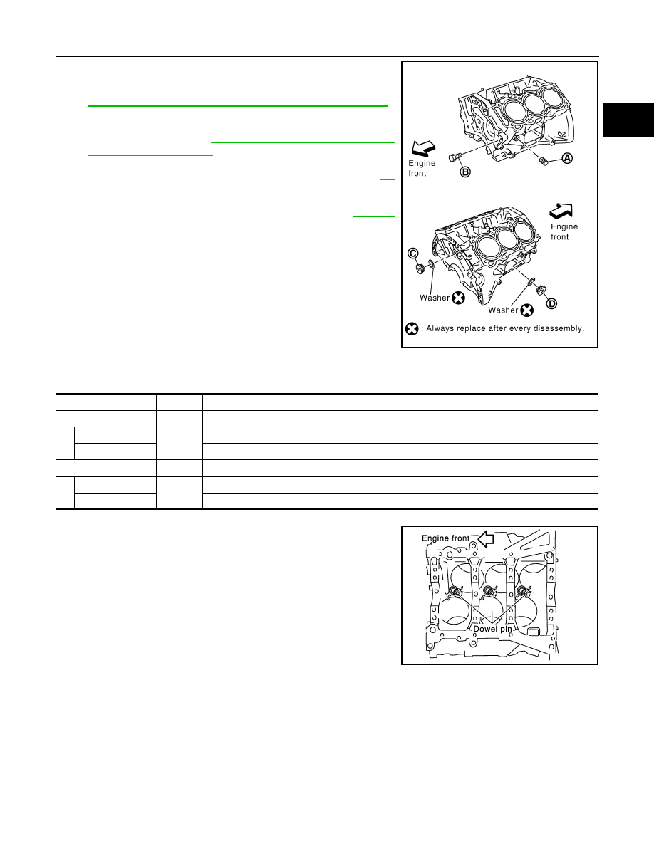
2. Install each plug to cylinder block as shown.

• Apply sealant to the thread of water drain plugs (A) and (B).

Use Genuine RTV Silicone Sealant or equivalent. Refer to

GI-21, "Recommended Chemical Products and Sealants"

.

• Apply sealant to the thread of plug (C).

Use Genuine High Strength Thread Locking Sealant or

equivalent. Refer to 

GI-21, "Recommended Chemical

Products and Sealants"

.

• Apply sealant to the threads of plug (D).

Use Anaerobic Liquid Gasket or equivalent. Refer to 

GI-

21, "Recommended Chemical Products and Sealants"

.

NOTE:

For Canada, (D) is not plug but block heater. Refer to 

EM-220,

"Disassembly and Assembly"

.

• Replace washers with new washers.

• Tighten each plug as specified below.

Block Plug and Block Heater Installation

3. Install oil jet.

• Insert oil jet dowel pin into cylinder block dowel pin hole, and

tighten bolts to specifications.

4. Install main bearings and thrust bearings as follows:
a. Remove dust, dirt, and engine oil on bearing mating surfaces of cylinder block and main bearing caps.

WLIA0020E

Part

Washer

Tightening Torque

A

No

19.6 N·m (2.0 kg-m, 14 ft-lb)

B

Reuse

No

9.8 N·m (1.0 kg-m, 87 in-lb)

New

6.0 N·m (0.61 kg-m, 53 in-lb)

C

Yes

116 N·m (11.8 kg-m, 86 ft-lb)

D

Plug

Yes

62 N·m (6.3 kg-m, 46 ft-lb)

Block heater

73.5 N·m (7.5 kg-m, 54 ft-lb)

Oil jet bolts

: 27.0 N·m (2.8 kg-m, 20 ft-lb)

PBIC0898E

EM-226

< UNIT DISASSEMBLY AND ASSEMBLY >

[VQ40DE]

ENGINE UNIT

b. Install thrust bearings to the both sides of the No. 3 journal hous-

ing on cylinder block.

• Install thrust bearings with the oil groove facing crankshaft arm

(outside).

• Install thrust bearing with a projection on one end on cylinder

block, Align projection with mating notch.

c.

Install main bearings paying attention to the direction.

• Main bearing with oil hole and groove goes on cylinder block.

The one without them goes on lower cylinder block.

• Before installing main bearings, apply engine oil to the bearing

surface (inside). Do not apply engine oil to the back surface,

but thoroughly clean it.

• When installing, align main bearing stopper protrusion to cut-

out of cylinder block and lower cylinder block.

• Ensure the oil holes on cylinder block and those on the corre-

sponding bearing are aligned.

5. Install crankshaft to cylinder block.

• While turning crankshaft by hand, check that it turns smoothly. 

6. Inspect the outer diameter of lower cylinder block bolt. Refer to 

EM-230, "Inspection After Disassembly"

.

7. Install lower cylinder block as follows:

NOTE:

Lower cylinder block cannot be replaced as a single part, because it is machined together with cylinder

block.

a. Apply a continuous bead of liquid gasket using Tool to lower cyl-

inder block as shown.

Use Genuine RTV Silicone Sealant or equivalent. Refer to

GI-21, "Recommended Chemical Products and Sealants"

.

CAUTION:

After liquid gasket is applied, rear oil seal installation must

be finished within 5 minutes. Therefore, the following pro-

cedure must be performed quickly.

b. Tighten lower cylinder block as follows:
i.

Apply new engine oil to threads and seat surfaces of the bolts.

ii.

Tighten M8 bolts in numerical order as shown from No. 17 to 24.

CAUTION:

Wipe off completely any protruding liquid gasket on rear oil

seal installation surface.

NOTE:

There are more processes to complete the tightening bolts.

However stop procedure here to install rear oil seal.

c.

Install rear oil seal. Refer to 

EM-203, "Removal and Installation of Rear Oil Seal"

.

d. Restart tightening of lower cylinder block bolts as follows:

PBIC2968E

PBIC2969E

Tool number

: WS39930000 (

)

Bolts 17 - 24

: 22.1 N·m (2.3 kg-m, 16 ft-lb)

PBIC2942E

PBIC2941E

ENGINE UNIT

EM-227

< UNIT DISASSEMBLY AND ASSEMBLY >

[VQ40DE]

C

D

E

F

G

H

I

J

K

L

M

A

EM

N

P

O

i.

Tighten M10 bolts in numerical order as shown from No. 1 to 16.

NOTE:

Use socket (size E14) for bolts No. 1 to 16 (M10 bolt).

ii.

Turn M10 bolts 90

° clockwise in numerical order from No. 1 to

16 using Tool.

CAUTION:

Use angle wrench Tool to check tightening angle. Do not

make judgement by visual inspection.

• After installing the bolts, make sure that crankshaft can be rotated smoothly by hand.

• Wipe off completely any protruding liquid gasket on front side of the engine.

• Check the crankshaft end play. Refer to 

EM-230, "Inspection After Disassembly"

.

8. Inspect the outer diameter of connecting rod bolt. Refer to 

EM-230, "Inspection After Disassembly"

.

9. Install piston to connecting rod as follows: 
a. Install new snap ring to the groove of piston rear side using suitable tool.

• Insert it fully into groove to install.

b. Install piston to connecting rod.

• Using industrial use drier or similar tool, heat piston until piston pin can be pushed in by hand without

excess force [approx. 60

° to 70 °C (140° to 158 °F)]. From the front to the rear, insert piston pin into pis-

ton and connecting rod.

• Assemble so that the front mark on the piston head and the

cylinder number on connecting rod are positioned as shown.

c. Install new snap ring to the groove of the piston front side. 

• Insert it fully into groove to install.

• After installing, make sure that connecting rod moves

smoothly.

10. Install piston rings using piston ring expander or suitable tool.

CAUTION:

• When installing piston rings, be careful not to damage

piston.

• Be careful not to damage piston rings by expending them

excessively.

Bolts 1 - 16

: 35.3 N·m (3.6 kg-m, 26 ft-lb)

PBIC2941E

Tool number

: KV10112100 (BT-8653-A)

WBIA0584E

SEM838F

PBIC0087E

EM-228

< UNIT DISASSEMBLY AND ASSEMBLY >

[VQ40DE]

ENGINE UNIT

• If there is stamped mark on ring, mount it with marked side up.

NOTE:

If there is no stamp on ring, no specific orientation is required

for installation.

• Position each ring with the gap as shown referring to the pis-

ton front mark.

• Check the piston ring side clearance. Refer to 

EM-230, "Inspection After Disassembly"

.

11. Install connecting rod bearings to connecting rod and connecting rod bearing cap.

• Before installing connecting rod bearings, apply engine oil to the bearing surface (inside). Do not apply

engine oil to the back surface, but thoroughly clean it. 

• When installing, align connecting rod bearing stopper protru-

sion with cutout of connecting rods and connecting rod bearing

caps to install. 

• Ensure the oil hole on connecting rod and that on the corre-

sponding bearing are aligned. 

12. Install piston and connecting rod assembly to crankshaft. 
13. Position crankshaft pin corresponding to connecting rod to be installed onto the bottom dead center.
14. Apply engine oil sufficiently to the cylinder bore, piston and crankshaft pin journal.
15. Match the cylinder position with the cylinder number on connecting rod to install. 

NOTE:

Be sure that front mark on piston head is facing front of engine.

16. Install piston with the front mark on the piston head facing the

front of engine using Tool.

CAUTION:

Be careful not to damage the cylinder wall and crankshaft

pin, resulting from an interference of the connecting rod big

end.

Stamped mark:

Top ring

: —

Second ring

: R

SEM757G

PBIC0808E

PBIC2067E

Tool number

: EM03470000 (J-8037)

WBIA0585E


Content   ..  757  758  759  760   ..