Nissan Frontier. Manual - part 753


  Index      Nissan     Nissan Frontier (2014 year) - Service and Repair Manual


Search            


Content   ..  751  752  753  754   ..


Nissan Frontier. Manual - part 753


CAMSHAFT

EM-201

< REMOVAL AND INSTALLATION >

[VQ40DE]

C

D

E

F

G

H

I

J

K

L

M

A

EM

N

P

O

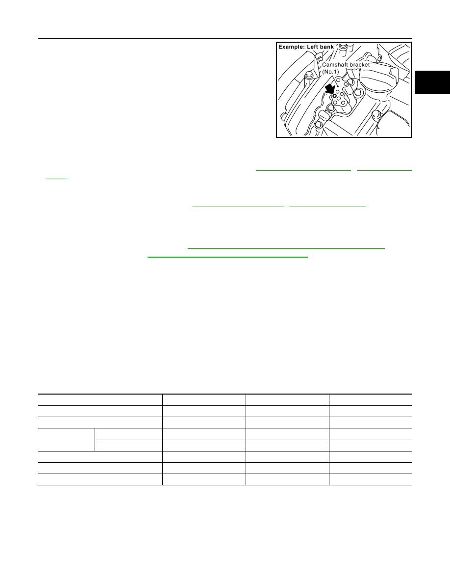
4. Crank the engine, and then make sure that engine oil comes out

from camshaft bracket (No. 1) oil hole. End cranking after check-

ing.

WARNING:

• Be careful not to touch rotating parts (drive belts, idler

pulley, and crankshaft pulley, etc.).

CAUTION:

• Engine oil may squirt from intake valve timing control

solenoid valve installation hole during cranking. Use a

shop cloth to prevent the engine components and the

vehicle.

• Do not allow engine oil to get on rubber components such

as drive belt or engine mount insulators. Immediately wipe off any splashed engine oil.

• Clean oil groove between oil strainer and intake valve timing control solenoid valve if engine oil does not

come out from camshaft bracket (No. 1) oil hole. Refer to 

LU-21, "Lubrication Circuit"

LU-21, "System

Chart"

.

5. Remove components between intake valve timing control solenoid valve and camshaft sprocket (INT),

and then check each oil groove for clogging.

• Clean oil groove if necessary. Refer to 

LU-21, "Lubrication Circuit"

LU-21, "System Chart"

.

6. After inspection, installation of the remaining components is in the reverse order of removal.

INSPECTION AFTER INSTALLATION

• Before starting engine, check oil/fluid levels including engine coolant and engine oil. If less than required

quantity, fill to the specified level. Refer to 

MA-16, "FOR USA AND CANADA : Fluids and Lubricants"

 (United

States and Canada). Refer to 

MA-18, "FOR MEXICO : Fluids and Lubricants"

 (Mexico).

• Use procedure below to check for fuel leakage.

• Turn ignition switch ON (with engine stopped). With fuel pressure applied to fuel piping, check for fuel leak-

age at connection points.

• Start engine. With engine speed increased, check again for fuel leakage at connection points.

• Run engine to check for unusual noise and vibration.

NOTE:

If hydraulic pressure inside timing chain tensioner drops after removal and installation, slack in the guide

may generate a pounding noise during and just after engine start. However, this is normal. Noise will stop

after hydraulic pressure rises.

• Warm up engine thoroughly to make sure there is no leakage of fuel, exhaust gas, or any oils/fluids including

engine oil and engine coolant.

• Bleed air from passages in lines and hoses, such as in cooling system.

• After cooling down engine, again check oil/fluid levels including engine oil and engine coolant. Refill to spec-

ified level, if necessary.

• Summary of the inspection items:

*Power steering fluid, brake fluid, etc.

PBIC2869E

Item

Before starting engine

Engine running

After engine stopped

Engine coolant

Level

Leakage

Level

Engine oil

Level

Leakage

Level

Transmission/
transaxle fluid 

A/T and CVT Models

Leakage

Level/Leakage

Leakage

M/T Models

Level/Leakage

Leakage

Level/Leakage

Other oils and fluids*

Level

Leakage

Level

Fuel

Leakage

Leakage

Leakage

Exhaust gas

Leakage

EM-202

< REMOVAL AND INSTALLATION >

[VQ40DE]

OIL SEAL

OIL SEAL

Removal and Installation of Valve Oil Seal

INFOID:0000000009478138

REMOVAL

1. Turn crankshaft until the cylinder requiring new oil seals is at TDC. This will prevent valve from dropping

into cylinder.

2. Remove camshaft relating to valve oil seal to be removed. Refer to 

EM-193, "Removal and Installation"

.

3. Remove valve lifters. Refer to 

EM-193, "Removal and Installation"

.

4. Remove valve collet, valve spring retainer and valve spring

using Tool.

CAUTION:

When working, take care not to damage valve lifter holes.

• Compress valve spring using Tool attachment, adapter.

Remove valve collet with magnet hand.

5. Remove valve oil seal using Tool.

INSTALLATION

1. Apply new engine oil to new valve oil seal joint surface and seal lip.
2. Press in valve oil seal to specified height (H) using Tool.

NOTE:

Dimension (H): height measured before valve spring seat instal-

lation.

3. Installation of the remaining components is in the reverse order

of removal.

Removal and Installation of Front Oil Seal

INFOID:0000000009478139

REMOVAL

1. Remove engine under cover. Refer to 

EXT-15, "Removal and Installation"

.

2. Remove drive belt. Refer to 

EM-129, "Removal and Installation"

.

3. Remove engine cooling fan assembly. Refer to 

CO-47, "Removal and Installation (Crankshaft driven

type)"

.

4. Remove crankshaft pulley. Refer to 

EM-168, "Removal and Installation"

.

Tool numbers

: KV10116200 (J-26336-B)
: KV10115900 (J-26336-20)
: KV10109220 ( — )

WBIA0578E

Tool number

: KV10107902 (J-38959)

WBIA0489E

Tool number

(J-39386)

Intake and exhaust

: 14.3 - 14.9 mm (0.563 - 0.587 in)

WBIA0490E

OIL SEAL

EM-203

< REMOVAL AND INSTALLATION >

[VQ40DE]

C

D

E

F

G

H

I

J

K

L

M

A

EM

N

P

O

5. Remove front oil seal using suitable tool.

CAUTION:

Be careful not to damage front timing chain case and crank-

shaft.

INSTALLATION

1. Apply new engine oil to both oil seal lip and dust seal lip of new front oil seal.
2. Install front oil seal.

• Install front oil seal so that each seal lip is oriented as shown.

• Press-fit until the height of front oil seal is level with the mount-

ing surface using suitable tool.

- Suitable drift: outer diameter 60 mm (2.36 in), inner diameter

50 mm (1.97 in).

CAUTION:

• Be careful not to damage front timing chain case and

crankshaft.

• Press-fit straight and avoid causing burrs or tilting oil

seal.

3. Installation is in the reverse order of removal after this step.

Removal and Installation of Rear Oil Seal

INFOID:0000000009478140

REMOVAL

1. Remove transmission assembly. Refer to 

TM-72, "Removal and Installation from Vehicle (For 2WD Mod-

els)"

 (2WD models), 

TM-74, "Removal and Installation from Vehicle (For 4WD Models)"

 (4WD models).

2. Remove drive plate. Refer to 

EM-219, "Exploded View"

.

3. Remove rear oil seal with a suitable tool.

CAUTION:

Be careful not to damage crankshaft and cylinder block.

PBIC2931E

SEM715A

PBIC2931E

PBIC2932E

EM-204

< REMOVAL AND INSTALLATION >

[VQ40DE]

OIL SEAL

INSTALLATION

1. Apply new engine oil to new rear oil seal joint surface and seal lip.
2. Install rear oil seal so that each seal lip is oriented as shown.

• Install new rear oil seal using Tool.

CAUTION:

• Be careful not to damage crankshaft and cylinder block.

• Press-fit oil seal straight to avoid causing burrs or tilt-

ing.

• Do not touch grease applied onto oil seal lip.

• Press in rear oil seal to the position as shown.

3. Installation of the remaining components is in the reverse order of removal.

CAUTION:

• When replacing an engine or transmission you must make sure the dowels are installed cor-

rectly during reassembly.

• Improper alignment caused by missing dowels may cause vibration, oil leaks or breakage of

drivetrain components.

SEM715A

Tool number

:    —   (J-49815)
:    —   (J-8092)

PBIC2933E

SBIA0281E


Content   ..  751  752  753  754   ..