Nissan Frontier. Manual - part 752


  Index      Nissan     Nissan Frontier (2014 year) - Service and Repair Manual


Search            


Content   ..  750  751  752  753   ..


Nissan Frontier. Manual - part 752


CAMSHAFT

EM-197

< REMOVAL AND INSTALLATION >

[VQ40DE]

C

D

E

F

G

H

I

J

K

L

M

A

EM

N

P

O

• Measure the outer diameter at 1/2 height of valve lifter with

micrometer since valve lifter is in barrel shape.

VALVE LIFTER HOLE DIAMETER

• Measure the inner diameter of valve lifter hole of cylinder head with

inside micrometer.

VALVE LIFTER CLEARANCE

• (Valve lifter clearance) = (Valve lifter hole diameter) – (Valve lifter outer diameter), Refer to 

EM-247, "Stan-

dard and Limit"

.

• If the calculated value is out of the standard, referring to each standard of valve lifter outer diameter and

valve lifter hole diameter, replace either or both valve lifter and cylinder head.

INSTALLATION

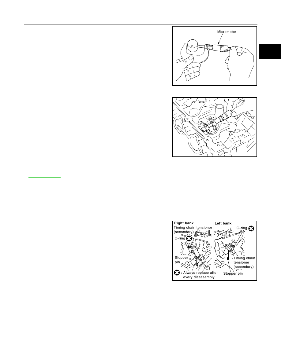
1. Install timing chain tensioners (secondary) on both sides of cyl-

inder head.

• Install timing chain tensioner with its stopper pin attached. 

• Install timing chain tensioner with sliding part facing downward

on right-side cylinder head, and with sliding part facing upward

on left-side cylinder head.

• Install new O-rings as shown.

CAUTION:

Do not reuse O-rings.

2. Install valve lifters.

• Install it in the original position.

3. Install camshafts.

Standard (Intake and exhaust)

: 33.977 - 33.987 mm (1.3377 - 1.3381 in)

JEM798G

Standard (Intake and exhaust)

: 34.000 - 34.016 mm (1.3386 - 1.3392 in)

SEM867E

Standard (Intake and exhaust)

: 0.013 - 0.039 mm (0.0005 - 0.0015 in)

PBIC2111E

EM-198

< REMOVAL AND INSTALLATION >

[VQ40DE]

CAMSHAFT

• Install camshaft with dowel pin attached to its front end face on

the exhaust side.

• Follow your identification marks made during removal, or fol-

low the identification marks that are present on new camshafts

for proper placement and direction.

• Install camshaft so that dowel pin hole and dowel pin on front

end face are positioned as shown. (No. 1 cylinder TDC on its

compression stroke)

NOTE:

• Large and small pin holes are located on front end face of

camshaft (INT), at intervals of 180

°. Face small dia. side pin

hole upward (in cylinder head upper face direction).

• Though camshaft does not stop at the portion as shown, for

the placement of cam nose, it is generally accepted cam-

shaft is placed for the same direction as shown.

KBIA1071E

Bank

INT/EXH

Dowel pin

Paint marks

Identification 

mark

M1

M2

RH

INT

No

Green

No

RE

EXH

Yes

No

White

RE

LH

INT

No

Green

No

LH

EXH

Yes

No

White

LH

KBIA1009E

PBIC2478E

CAMSHAFT

EM-199

< REMOVAL AND INSTALLATION >

[VQ40DE]

C

D

E

F

G

H

I

J

K

L

M

A

EM

N

P

O

4. Install camshaft brackets.

• Remove foreign material completely from camshaft bracket

backside and from cylinder head installation face.

• Install camshaft bracket in original position and direction as

shown.

• Install camshaft brackets (No. 2 to 4) aligning the stamp marks

as shown.

NOTE:

There are no identification marks indicating left and right for

camshaft bracket (No. 1).

• Apply liquid gasket to mating surface of camshaft bracket (No.

1) as shown on right and left banks.

Use Genuine RTV Silicone Sealant or equivalent. Refer to

GI-21, "Recommended Chemical Products and Sealants"

.

PBIC2051E

PBIC2052E

PBIC2660E

EM-200

< REMOVAL AND INSTALLATION >

[VQ40DE]

CAMSHAFT

5. Tighten camshaft bracket bolts in the following steps, in numeri-

cal order as shown.

6. Measure the difference in levels between front end faces of

camshaft bracket (No. 1) and cylinder head. 

• Measure two positions (both intake and exhaust side) for a

single bank.

• If the measured value is out of the standard, re-install cam-

shaft bracket (No. 1).

7. Check and adjust the valve clearance. Refer to 

EM-247, "Standard and Limit"

.

8. Installation of the remaining components is in the reverse order of removal.

INSPECTION AFTER INSTALLATION

Inspection of Camshaft Sprocket (INT) Oil Groove

WARNING:

• Check when engine is cold so as to prevent burns from any splashing engine oil.

CAUTION:

• Perform this inspection only when DTC P0011 or P0021 are detected in self-diagnostic results of

CONSULT and it is directed according to inspection procedure of EC section. Refer to 

EC-621, "DTC

Confirmation Procedure"

.

1. Check the engine oil level. Refer to 

LU-22, "Inspection"

.

2. Perform the following procedure so as to prevent the engine from being unintentionally started while

checking.

a. Release fuel pressure. Refer to 

EC-959, "Fuel Pressure Check"

.

b. Disconnect harness connectors from ignition coil and injector .
3. Remove intake valve timing control solenoid valve. Refer to 

EM-168, "Removal and Installation"

.

Camshaft bracket bolts
Step 1 (bolts 7 - 10)

: 1.96 N·m (0.2 kg-m, 17 in-lb)

Step 2 (bolts 1 - 6)

: 1.96 N·m (0.2 kg-m, 17 in-lb)

Step 3 (bolts 1 - 10)

: 5.88 N·m (0.6 kg-m, 52 in-lb)

Step 4 (bolts 1 - 10)

: 10.4 N·m (1.1 kg-m, 92 in-lb)

PBIC2050E

Standard : –0.14 to 0.14 mm (–0.0055 to 0.0055 in) 

EMQ0044D


Content   ..  750  751  752  753   ..