Nissan Frontier. Manual - part 747


  Index      Nissan     Nissan Frontier (2014 year) - Service and Repair Manual


Search            


Content   ..  745  746  747  748   ..


Nissan Frontier. Manual - part 747


TIMING CHAIN

EM-177

< REMOVAL AND INSTALLATION >

[VQ40DE]

C

D

E

F

G

H

I

J

K

L

M

A

EM

N

P

O

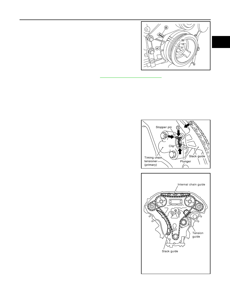
1. Set No. 1 cylinder to TDC.

• Rotate crankshaft pulley clockwise to align timing mark (A)

(grooved line without color) with timing indicator (B).

2. Remove front timing chain case. Refer to 

EM-168, "Removal and Installation"

.

3. Check timing chain markings to confirm No. 1 cylinder is at TDC of its compression stroke.

• If not, remove Ring Gear Stopper Tool and turn crankshaft clockwise 360

° (one revolution).

• Re-install Ring Gear Stopper Tool.

• If the original timing chain markings are not legible, use paint or equivalent to mark the timing chains to

the sprockets.

4. If removing the secondary timing chains, loosen camshaft sprocket bolts.
5. Compress the primary timing chain tensioner.

1. Loosen clip of primary timing chain tensioner, and release

plunger stopper (1).

2. Depress plunger into tensioner body by pressing slack

guide (2).

3. Keep slack guide pressed and insert stopper pin through

the tensioner body hole and plunger groove (3) to hold

plunger in.

NOTE:

Use stopper pin included with Tool J-50246.

6. Remove internal chain guide.

7. Remove timing chain (primary).

CAUTION:

AWBIA0719ZZ

Tool number

: KV11105210 (J-44716)

PBIC2919E

PBIC2266E

EM-178

< REMOVAL AND INSTALLATION >

[VQ40DE]

TIMING CHAIN

After removing timing chain (primary), do not turn crankshaft and camshaft separately, or valves

will strike the piston heads.

8. Remove crankshaft sprocket, if necessary.
9. Remove timing chain (secondary) and camshaft sprockets as follows:
a. Attach stopper pin to the right and left timing chain tensioners

(secondary).

NOTE:

• Use stopper pin included with Tool J-50246.

b. Remove camshaft sprocket (INT and EXH) bolts.
c.

Remove timing chain (secondary) together with camshaft sprockets.

• Turn camshaft slightly to secure slack of timing chain on timing chain tensioner (secondary) side.

• Insert 0.5 mm (0.020 in)-thick metal or resin plate between tim-

ing chain and timing chain tensioner plunger (guide). Remove

timing chain (secondary) together with camshaft sprockets

with timing chain loose from guide groove.

CAUTION:

Be careful of plunger coming off when removing timing

chain (secondary). 

NOTE:

Camshaft sprocket (INT) is a one piece integrated design with

sprockets for timing chain (primary) and for timing chain (sec-

ondary).

• When handling camshaft sprocket (INT), be careful of the fol-

lowing:

CAUTION:

• Handle carefully to avoid any shock to camshaft

sprocket.

• Do not disassemble. (Do not loosen bolts (A) as shown).

NOTE:

For removal of timing chain tensioner (secondary), refer to 

EM-

185, "Removal and Installation (Secondary Timing Chain Ten-

sioner)"

. [Removing camshaft bracket (No. 1) is required.]

INSPECTION AFTER REMOVAL

Check for cracks and any excessive wear at link plates. Replace

chain if necessary.

• Inspect all timing chains and associated parts for wear or damage,

replace as necessary.

INSTALLATION

PBIC2047E

PBIC1978E

PBIC2920E

PBIC0282E

TIMING CHAIN

EM-179

< REMOVAL AND INSTALLATION >

[VQ40DE]

C

D

E

F

G

H

I

J

K

L

M

A

EM

N

P

O

NOTE:

The figure above shows the relationship between the mating mark on each timing chain and that on the corre-

sponding sprocket, with the components installed.
1. Make sure that dowel pin hole, dowel pin of camshaft and crank-

shaft key are located as shown. (No. 1 cylinder at compression

TDC)

NOTE:

Though camshaft does not stop at the position as shown, for the

placement of cam nose, it is generally accepted camshaft is

placed for the same direction of the figure.

2. Install timing chains (secondary) and camshaft sprockets as follows:

CAUTION:

Mating marks between timing chain and sprockets slip easily. Confirm all mating mark positions

repeatedly during the installation process.

1.

Internal chain guide

2.

Camshaft sprocket (intake)

3.

Mating mark (blue link)

4.

Mating mark (punched)

5.

Secondary timing chain tensioner

6.

Mating mark (copper link)

7.

Secondary timing chain

8.

Camshaft sprocket (exhaust)

9.

Tensioner guide

10. Water pump

11. Crankshaft sprocket

12. Mating mark (notched)

13. Primary timing chain

14. Slack guide

15. Primary timing chain tensioner

16. Mating mark (back side)

17. Crankshaft key

Camshaft dowel pin hole (intake side)

: At cylinder head upper face side in each bank.

Camshaft dowel pin (exhaust side)

: At cylinder head upper face side in each bank.

Crankshaft key

: At cylinder head side of right bank.

AWBIA1011GB

KBIA1073E

EM-180

< REMOVAL AND INSTALLATION >

[VQ40DE]

TIMING CHAIN

a. Push plunger of timing chain tensioner (secondary) and keep it

pressed in with stopper pin.

• Use stopper pin included with Tool J-50246.

b. Before installing timing chains (secondary) and camshaft

sprockets, confirm mating marks are visible. If necessary, use

paint or equivalent to re-mark the camshaft sprockets at each

mating mark.

c.

Install timing chains (secondary) (8) and camshaft sprockets

[INT (1) and EXH (9)].

• Left bank mating marks (6)

• Align the timing chain mating marks (secondary) (2) (blue

color link) with the ones on camshaft sprockets (INT and EXH)

(4), (5), (7) and (10) (punched), and install them.

NOTE:

• Mating marks for camshaft sprocket (INT) are on the back

side of camshaft sprocket (secondary).

• There are two types of mating marks, circle (7), (10) and

oval (4), (5) types. They should be used for the right and left

banks, respectively.

• Align dowel pin (3) and pin hole on camshafts with the groove

(11) and dowel pin on sprockets, and install them.

• On the intake side, align pin hole on the small diameter side of

the camshaft front end with dowel pin (3) on the back side of

camshaft sprocket, and install them.

• On the exhaust side, align dowel pin on camshaft front end

with pin groove (11) on camshaft sprocket, and install them.

• In case that positions of each mating mark and each dowel pin

do not fit on mating parts, make fine adjustment to the position by slightly turning camshaft(s).

• Bolts for camshaft sprockets must be tightened in the next step. Tightening them by hand is enough to

prevent the dislocation of dowel pins.

d. Confirm the mating marks are aligned, then finger tighten camshaft sprocket bolts. Final tightening will be

done with all timing chains installed.

SEM430G

SEM811G

Right bank

: Use circle type (7) and (10).

Left bank

: Use oval type (4) and (5).

WBIA0689E


Content   ..  745  746  747  748   ..