Nissan Frontier. Manual - part 712
ROCKER COVER
EM-37
< REMOVAL AND INSTALLATION >
[QR25DE]
C
D
E
F
G
H
I
J
K
L
M
A
EM
N
P
O
ROCKER COVER
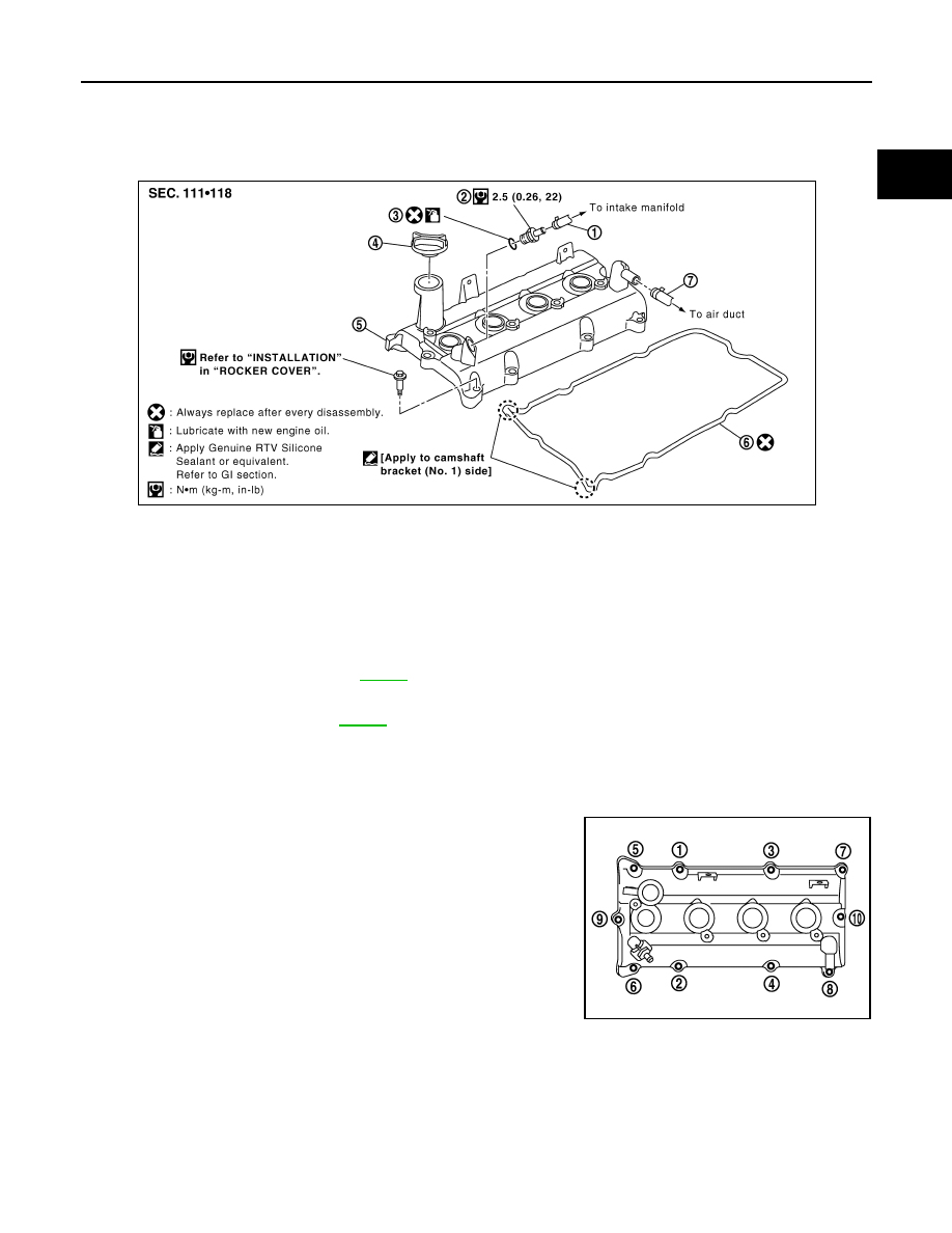
Exploded View
INFOID:0000000009478059
Removal and Installation
INFOID:0000000009478060
REMOVAL
1. Remove intake manifold. Refer to
.
2. Disconnect PCV hose from rocker cover.
3. Remove ignition coils. Refer to
.
4. Remove PCV valve and O-ring from rocker cover, if necessary.
CAUTION:
Do not reuse O-rings.
5. Remove oil filler cap from rocker cover, if necessary.
6. Loosen bolts in reverse order as shown.
7. Remove rocker cover gasket from rocker cover.
8. Use scraper to remove all traces of liquid gasket from cylinder head and camshaft bracket (No. 1).
CAUTION:
Do not scratch or damage the mating surface when cleaning off old liquid gasket.
INSTALLATION
1.
PCV hose
2.
PCV valve
3.
O-ring
4.
Oil filler cap
5.
Rocker cover
6.
Rocker cover gasket
7.
PCV hose
WBIA0650E
PBIC3003E