Nissan Frontier. Manual - part 711
OIL PAN
EM-33
< REMOVAL AND INSTALLATION >
[QR25DE]
C
D
E
F
G
H
I
J
K
L
M
A
EM
N
P
O
OIL PAN
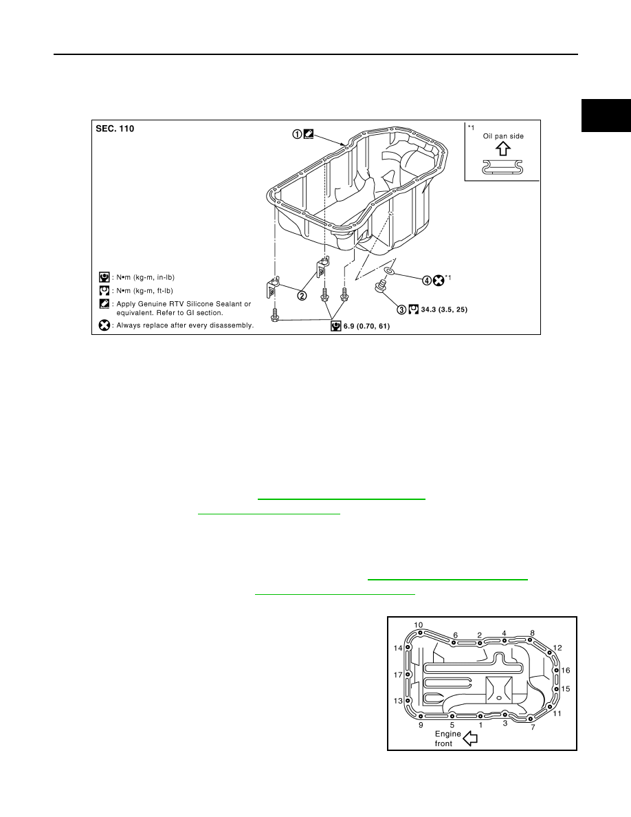
Exploded View
INFOID:0000000009478055
Removal and Installation
INFOID:0000000009478056
REMOVAL
WARNING:
To avoid the danger of being scalded, do not drain engine oil when engine is hot.
NOTE:
When removing components such as hoses, tubes/lines, etc., cap or plug openings to prevent fluid from spill-
ing.
1. Remove engine under cover. Refer to
EXT-15, "Removal and Installation"
.
2. Drain engine oil. Refer to
CAUTION:
• Perform this step when the engine is cold.
• Do not spill engine oil on drive belt.
3. Remove 3rd crossmember assembly.
4. Remove lower joint shaft pinch bolt at steering gear. Refer to
ST-12, "Removal and Installation"
.
5. Remove steering gear bolts. Refer to
ST-15, "Removal and Installation"
.
6. Remove oil pan with the following procedure:
a. Loosen bolts in reverse order as shown with power tool.
Remove A/T fluid cooler tube bracket (A/T models).
1.
Oil pan
2.
A/T fluid cooler tube bracket (A/T models)
3.
Drain plug
4.
Drain plug washer
PBIC2992E
PBIC2993E