Nissan Frontier. Manual - part 700
VIAS
EC-1371
< DTC/CIRCUIT DIAGNOSIS >
[VQ40DE FOR MEXICO]
C
D
E
F
G
H
I
J
K
L
M
A
EC
N
P
O
7.
DETECT MALFUNCTIONING PART
Check the following.
• Harness connectors E2, F32
• Harness for open or short between VIAS control solenoid valve and IPDM E/R
• Harness for open or short between VIAS control solenoid valve and ECM
>> Repair harness or connectors.
8.
CHECK VIAS CONTROL SOLENOID VALVE OUTPUT SIGNAL CIRCUIT FOR OPEN AND SHORT
1. Turn ignition switch OFF.
2. Disconnect ECM harness connector.
3. Check harness continuity between ECM terminal 29 and VIAS control solenoid valve terminal 2.
Refer to Wiring Diagram.
4. Also check harness for short to ground and short to power.
OK or NG
OK
>> GO TO 9.
NG
>> Repair open circuit or short to ground or short to power in harness or connectors.
9.
CHECK VIAS CONTROL SOLENOID VALVE
EC-1371, "Component Inspection"
.
OK or NG
OK
>> GO TO 10.
NG
>> Replace VIAS control solenoid valve. Refer to
10.
CHECK INTERMITTENT INCIDENT
GI-42, "Intermittent Incident"
.
>> INSPECTION END
Component Inspection
INFOID:0000000009482048
VIAS CONTROL SOLENOID VALVE
With CONSULT
1. Reconnect harness connectors disconnected.
2. Turn ignition switch ON.
3. Perform “VIAS S/V-1” in “ACTIVE TEST” mode.
4. Check air passage continuity and operation delay time under the
following conditions.
Operation takes less than 1 second.
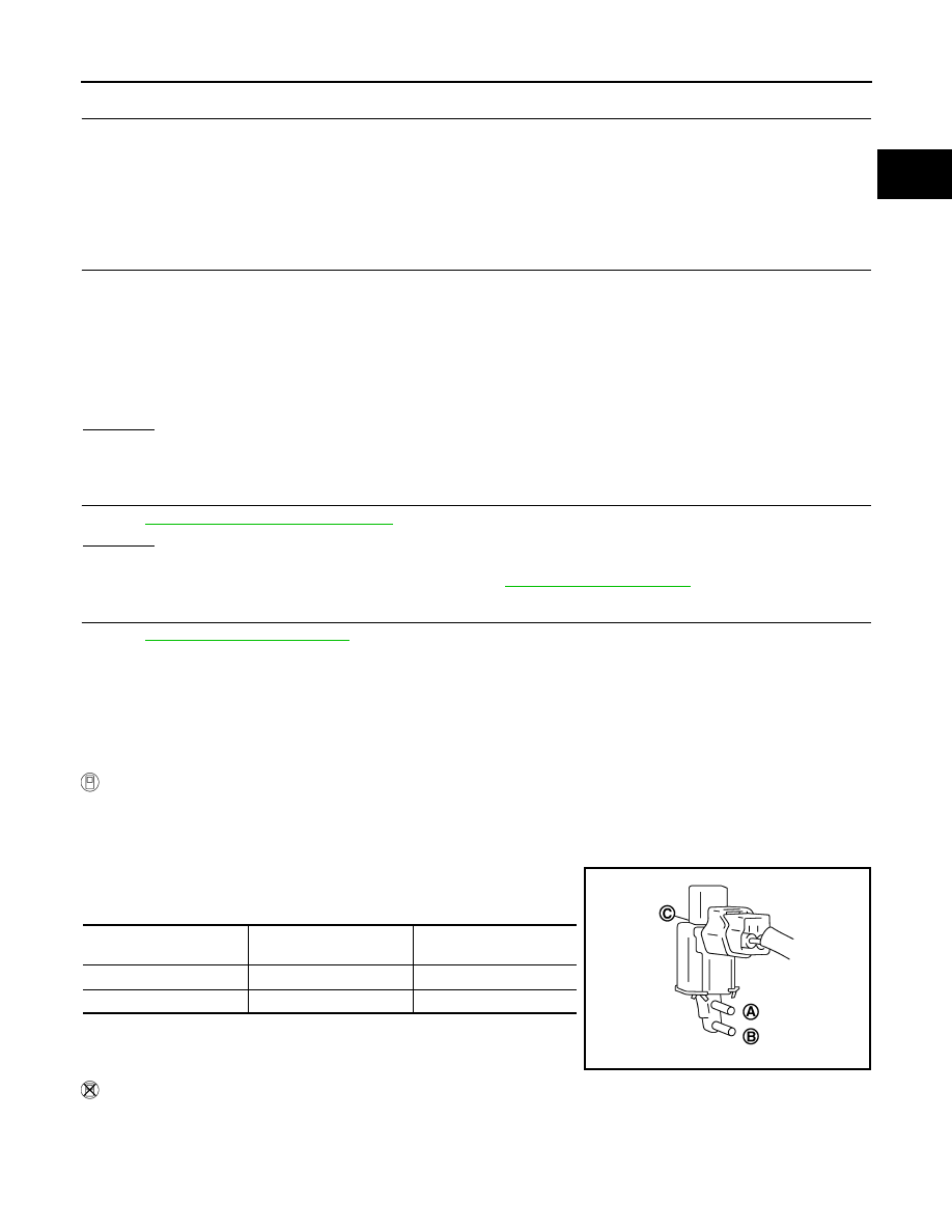
Without CONSULT
Continuity should exist.
Condition
VIAS SOL VALVE
Air passage continuity
between (A) and (B)
Air passage continuity
between (A) and (C)
ON
Yes
No
OFF
No
Yes
JMBIA0180ZZ