Nissan Frontier. Manual - part 682


  Index      Nissan     Nissan Frontier (2014 year) - Service and Repair Manual


Search            


Content   ..  680  681  682  683   ..


Nissan Frontier. Manual - part 682


P1800 VIAS CONTROL SOLENOID VALVE 1

EC-1299

< DTC/CIRCUIT DIAGNOSIS >

[VQ40DE FOR MEXICO]

C

D

E

F

G

H

I

J

K

L

M

A

EC

N

P

O

P1800 VIAS CONTROL SOLENOID VALVE 1

Component Description

INFOID:0000000009481969

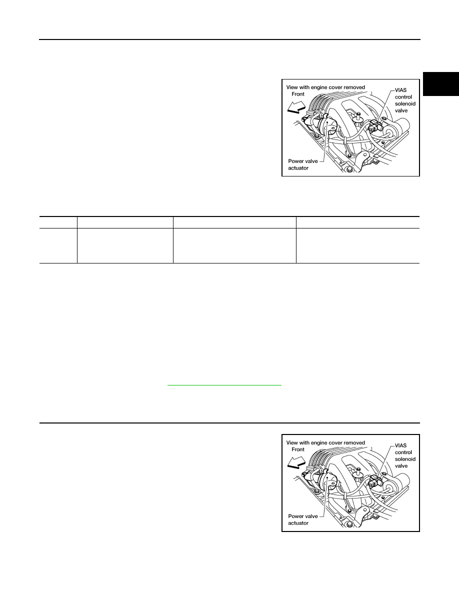
The VIAS control solenoid valve cuts the intake manifold vacuum

signal for power valve control. It responds to ON/OFF signals from

the ECM. When the solenoid is off, the vacuum signal from the

intake manifold is cut. When the ECM sends an ON signal the coil

pulls the plunger downward and sends the vacuum signal to the

power valve actuator.

On Board Diagnosis Logic

INFOID:0000000009481970

The MIL will not illuminate for this self-diagnosis.

DTC Confirmation Procedure

INFOID:0000000009481971

NOTE:

If DTC Confirmation Procedure has been previously conducted, always perform the following before conduct-

ing the next step.

1. Turn ignition switch OFF and wait at least 10 seconds.

2. Turn ignition switch ON.

3. Turn ignition switch OFF and wait at least 10 seconds.

TESTING CONDITION:

Before performing the following procedure, confirm that battery voltage is between 11V at idle.
1. Start engine and let it idle for at least 5 seconds.
2. Check 1st trip DTC.
3. If 1st trip DTC is detected, go to 

EC-1299, "Diagnosis Procedure"

.

Diagnosis Procedure

INFOID:0000000009481972

1.

CHECK VIAS CONTROL SOLENOID VALVE POWER SUPPLY CIRCUIT

1. Turn ignition switch OFF.

2. Disconnect VIAS control solenoid valve harness connector.

3. Turn ignition switch ON.

BBIA0569E

DTC No.

Trouble diagnosis name

DTC detecting condition

Possible cause

P1800
1800

VIAS control solenoid valve cir-
cuit 

An excessively low or high voltage signal 
is sent to ECM through the valve

• Harness or connectors

(The solenoid valve circuit is open or 
shorted.)

• VIAS control solenoid valve

BBIA0569E

EC-1300

< DTC/CIRCUIT DIAGNOSIS >

[VQ40DE FOR MEXICO]

P1800 VIAS CONTROL SOLENOID VALVE 1

4. Check voltage between terminal 1 and ground with CONSULT

or tester.

OK or NG

OK

>> GO TO 3.

NG

>> GO TO 2.

2.

DETECT MALFUNCTIONING PART

Check the following.

• Harness connectors E2, F32

• Harness for open or short between VIAS control solenoid valve and IPDM E/R

• Harness for open or short between VIAS control solenoid valve and ECM

>> Repair harness or connectors.

3.

CHECK VIAS CONTROL SOLENOID VALVE OUTPUT SIGNAL CIRCUIT FOR OPEN AND SHORT

1. Turn ignition switch OFF.

2. Disconnect ECM harness connector.

3. Check harness continuity between ECM terminal 29 and VIAS control solenoid valve terminal 2.

Refer to Wiring Diagram.

4. Also check harness for short to ground and short to power.
OK or NG

OK

>> GO TO 4.

NG

>> Repair open circuit or short to ground or short to power in harness or connectors.

4.

CHECK VIAS CONTROL SOLENOID VALVE

Refer to 

EC-1300, "Component Inspection"

.

OK or NG

OK

>> GO TO 5.

NG

>> Replace VIAS control solenoid valve. Refer to 

EM-142, "Exploded View"

.

5.

CHECK INTERMITTENT INCIDENT

Refer to 

GI-42, "Intermittent Incident"

.

>> INSPECTION END

Component Inspection

INFOID:0000000009481973

VIAS CONTROL SOLENOID VALVE

 With CONSULT

1. Reconnect harness connectors disconnected.
2. Turn ignition switch ON.
3. Perform “VIAS S/V-1” in “ACTIVE TEST” mode.

Voltage: Battery voltage

PBIB0173E

Continuity should exist.

P1800 VIAS CONTROL SOLENOID VALVE 1

EC-1301

< DTC/CIRCUIT DIAGNOSIS >

[VQ40DE FOR MEXICO]

C

D

E

F

G

H

I

J

K

L

M

A

EC

N

P

O

4. Check air passage continuity and operation delay time under the

following conditions.

Operation takes less than 1 second.

 With GST

Check air passage continuity and operation delay time under the fol-

lowing conditions.

Operation takes less than 1 second.

Condition

VIAS SOL VALVE

Air passage continuity 

between (A) and (B)

Air passage continuity 

between (A) and (C)

ON

Yes

No

OFF

No

Yes

JMBIA0180ZZ

Condition

Air passage continuity 

between (A) and (B)

Air passage continuity 

between (A) and (C)

12V direct current supply 
between terminals 1 and 2

Yes

No

No supply

No

Yes

PBIB2532E

EC-1302

< DTC/CIRCUIT DIAGNOSIS >

[VQ40DE FOR MEXICO]

P1805 BRAKE SWITCH

P1805 BRAKE SWITCH

Description

INFOID:0000000009481974

Brake switch signal is applied to the ECM through the stop lamp switch when the brake pedal is depressed.

This signal is used mainly to decrease the engine speed when the vehicle is being driven.

On Board Diagnosis Logic

INFOID:0000000009481975

The MIL will not illuminate for this diagnosis.

FAIL-SAFE MODE

When the malfunction is detected, the ECM enters fail-safe mode.

DTC Confirmation Procedure

INFOID:0000000009481976

NOTE:

If DTC Confirmation Procedure has been previously conducted, always turn ignition switch OFF and wait at

least 10 seconds before conducting the next test.
1. Turn ignition switch ON.
2. Fully depress the brake pedal for at least 5 seconds.
3. Erase the DTC with CONSULT.
4. Check 1st trip DTC.
5. If 1st trip DTC is detected, go to 

EC-1302, "Diagnosis Procedure"

.

Diagnosis Procedure

INFOID:0000000009481977

1.

CHECK STOP LAMP SWITCH CIRCUIT

1. Turn ignition switch OFF.

2. Check the stop lamp when depressing and releasing the brake pedal.

OK or NG

OK

>> GO TO 4.

NG

>> GO TO 2.

2.

CHECK STOP LAMP SWITCH POWER SUPPLY CIRCUIT 

DTC No.

Trouble diagnosis name

DTC detecting condition

Possible cause

P1805
1805

Brake switch

A brake switch signal is not sent to ECM for ex-
tremely long time while the vehicle is being driv-
en.

• Harness or connectors

(Stop lamp switch circuit is open or short-
ed.)

• Stop lamp switch

Engine operating condition in fail-safe mode

ECM controls the electric throttle control actuator by regulating the throttle opening to a small range.
Therefore, acceleration will be poor.

Vehicle condition

Driving condition

When engine is idling

Normal

When accelerating

Poor acceleration

Brake pedal

Stop lamp

Fully released

Not illuminated

Slightly depressed

Illuminated


Content   ..  680  681  682  683   ..