Nissan Frontier. Manual - part 672
P0850 PNP SWITCH
EC-1259
< DTC/CIRCUIT DIAGNOSIS >
[VQ40DE FOR MEXICO]
C
D
E
F
G
H
I
J
K
L
M
A
EC
N
P
O
P0850 PNP SWITCH
Component Description
INFOID:0000000009481911
When the selector lever position is P or N, park/neutral position (PNP) signal is sent to ECM from TCM via
combination meter (unified meter control unit).
ECM detects the position because the continuity of the line (the ON signal) exists.
On Board Diagnosis Logic
INFOID:0000000009481912
DTC Confirmation Procedure
INFOID:0000000009481913
CAUTION:
Always drive vehicle at a safe speed.
NOTE:
If DTC Confirmation Procedure has been previously conducted, always perform the following before conduct-
ing the next step.
1. Turn ignition switch OFF and wait at least 10 seconds.
2. Turn ignition switch ON.
3. Turn ignition switch OFF and wait at least 10 seconds.
WITH CONSULT
1. Turn ignition switch ON.
2. Select “P/N POSI SW” in “DATA MONITOR” mode with CONSULT. Then check the “P/N POSI SW” signal
under the following conditions.
If NG, go to
EC-1260, "Diagnosis Procedure"
.
If OK, go to following step.
3. Select “DATA MONITOR” mode with CONSULT.
4. Start engine and warm it up to normal operating temperature.
5. Maintain the following conditions for at least 60 consecutive seconds.
6. Check 1st trip DTC.
7. If 1st trip DTC is detected, go to
EC-1260, "Diagnosis Procedure"
Overall Function Check
INFOID:0000000009481914
Use this procedure to check the overall function of the park/neutral position (PNP) signal circuit. During this
check, a 1st trip DTC might not be confirmed.
WITH GST
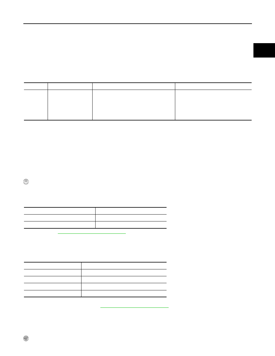
DTC No.
Trouble diagnosis name
DTC detecting condition
Possible cause
P0850
0850
Park/neutral position
switch
The park/neutral position (PNP) signal not
change during driving after the engine in start-
ed.
• Harness or connectors
[The park/neutral position (PNP) signal
circuit is open or shorted.]
• Transmission range switch
• Combination meter
• TCM
Position (Selector lever)
Known-good signal
P or N position
ON
Except above position
OFF
ENG SPEED
1,400 - 6,375 rpm
COOLAN TEMP/S
More than 70
°C (158°F)
B/FUEL SCHDL
2.0 - 31.8 msec
VHCL SPEED SE
More than 64 km/h (40 MPH)
Selector lever
Suitable position