Nissan Frontier. Manual - part 662
P0443 EVAP CANISTER PURGE VOLUME CONTROL SOLENOID VALVE
EC-1219
< DTC/CIRCUIT DIAGNOSIS >
[VQ40DE FOR MEXICO]
C
D
E
F
G
H
I
J
K
L
M
A
EC
N
P
O
DTC Confirmation Procedure
INFOID:0000000009481860
Perform PROCEDURE FOR MALFUNCTION A first.
If the DTC cannot be confirmed, perform PROCEDURE FOR MALFUNCTION B.
NOTE:
If DTC Confirmation Procedure has been previously conducted, always turn ignition switch OFF and wait at
least 10 seconds before conducting the next test.
PROCEDURE FOR MALFUNCTION A
TESTING CONDITION:
• Perform “DTC Confirmation Procedure” when the fuel level is between 1/4 and 3/4 full, and vehicle is placed
on flat level surface.
• Always perform test at a temperature of 5 to 60
°C (41 to 140°F).
• Cool the vehicle so that engine coolant temperature becomes same level as ambient temperature.
With CONSULT
1. Turn ignition switch ON and select “DATA MONITOR” mode with CONSULT.
2. Check that the following condition are met.
FUEL T/TMP SE: 0 – 35
°C (32 – 95°F)
3. Start engine and wait at least 60 seconds.
4. Check 1st trip DTC.
5. If 1st trip DTC is detected, go to
EC-1220, "Diagnosis Procedure"
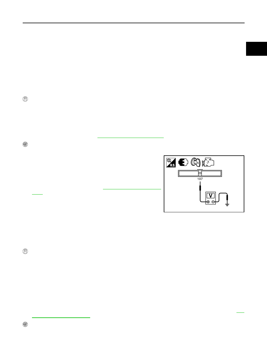
With GST
1. Turn ignition switch ON.
2. Set voltmeter probes to ECM terminal 107 (FTT sensor signal)
and ground.
3. Check that the voltage is 3.1 – 4.2 V.
4. Start engine and wait at least 60 seconds.
5. Check 1st trip DTC.
6. If 1st trip DTC is detected, go to
PROCEDURE FOR MALFUNCTION B
NOTE:
If DTC Confirmation Procedure has been previously conducted, always turn ignition switch OFF and wait at
least 10 seconds before conducting the next test.
TESTING CONDITION:
Always perform test at a temperature of 5
°C (41°F) or more.
With CONSULT
1. Start engine and warm it up to normal operating temperature.
2. Turn ignition switch OFF and wait at least 10 seconds.
3. Turn ignition switch ON.
4. Select “PURG VOL CN/V P1444” of “EVAPORATIVE SYSTEM” in “DTC WORK SUPPORT” mode with
CONSULT.
5. Touch “START”.
6. Start engine and let it idle until “TESTING” on CONSULT changes to “COMPLETED”. (It will take approxi-
mately 10 seconds.)
If “TESTING” is not displayed after 5 minutes, retry from step 2.
7. Check that “OK” is displayed after touching “SELF-DIAG RESULTS”. If “NG” is displayed, refer to
.
With GST
JPBIA4822ZZ