Nissan Frontier. Manual - part 638


  Index      Nissan     Nissan Frontier (2014 year) - Service and Repair Manual


Search            


Content   ..  636  637  638  639   ..


Nissan Frontier. Manual - part 638


P0122, P0123 TP SENSOR

EC-1123

< DTC/CIRCUIT DIAGNOSIS >

[VQ40DE FOR MEXICO]

C

D

E

F

G

H

I

J

K

L

M

A

EC

N

P

O

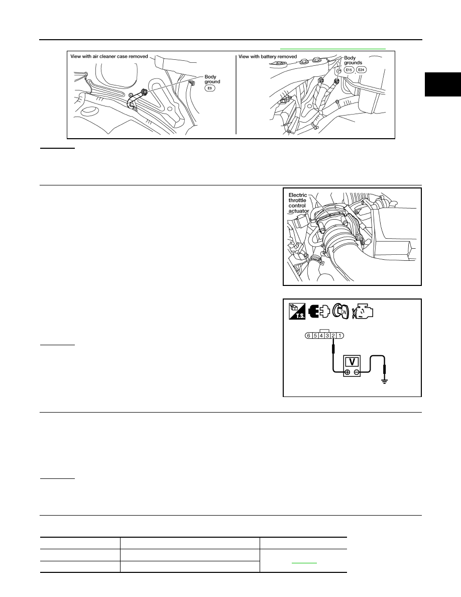
2. Loosen and retighten three ground screws on the body. Refer to 

EC-1094, "Ground Inspection"

.

OK or NG

OK

>> GO TO 2.

NG

>> Repair or replace ground connections.

2.

CHECK THROTTLE POSITION SENSOR 2 POWER SUPPLY CIRCUIT-I

1. Disconnect electric throttle control actuator harness connector.

2. Turn ignition switch ON.

3. Check voltage between electric throttle control actuator terminal

2 and ground with CONSULT or tester.

OK or NG

OK

>> GO TO 7.

NG

>> GO TO 3.

3.

CHECK THROTTLE POSITION SENSOR 2 POWER SUPPLY CIRCUIT-II

1. Turn ignition switch OFF.

2. Disconnect ECM harness connector.

3. Check harness continuity between electric throttle control actuator terminal 2 and ECM terminal 47.

Refer to Wiring Diagram.

OK or NG

OK

>> GO TO 4.

NG

>> Repair open circuit.

4.

CHECK THROTTLE POSITION SENSOR 2 POWER SUPPLY CIRCUIT-III

Check harness for short to power and short to ground, between the following terminals.

BBIA0539E

BBIA0543E

Voltage: Approximately 5V

PBIB2604E

Continuity should exist.

ECM terminal

Sensor terminal

Reference Wiring Diagram

47

Electric throttle control actuator terminal 2

EC-1043

91

APP sensor terminal 1

EC-1124

< DTC/CIRCUIT DIAGNOSIS >

[VQ40DE FOR MEXICO]

P0122, P0123 TP SENSOR

OK or NG

OK

>> GO TO 5.

NG

>> Repair short to ground or short to power in harness or connectors.

5.

CHECK APP SENSOR

Refer to 

EC-1328, "Component Inspection"

.

OK or NG

OK

>> GO TO 11.

NG

>> GO TO 6.

6.

REPLACE ACCELERATOR PEDAL ASSEMBLY

1. Replace accelerator pedal assembly. Refer to 

ACC-3, "Component"

.

2. Perform 

EC-1074, "Accelerator Pedal Released Position Learning"

.

3. Perform 

EC-1075, "Throttle Valve Closed Position Learning"

.

4. Perform 

EC-1075, "Idle Air Volume Learning"

.

>> INSPECTION END

7.

CHECK THROTTLE POSITION SENSOR 2 GROUND CIRCUIT FOR OPEN AND SHORT

1. Turn ignition switch OFF.

2. Disconnect ECM harness connector.

3. Check harness continuity between electric throttle control actuator terminal 4 and ECM terminal 66.

Refer to Wiring Diagram.

4. Also check harness for short to ground and short to power.
OK or NG

OK

>> GO TO 8.

NG

>> Repair open circuit or short to ground or short to power in harness or connectors.

8.

CHECK THROTTLE POSITION SENSOR 2 INPUT SIGNAL CIRCUIT FOR OPEN AND SHORT

1. Check harness continuity between ECM terminal 69 and electric throttle control actuator terminal 3.

Refer to Wiring Diagram.

2. Also check harness for short to ground and short to power.
OK or NG

OK

>> GO TO 9.

NG

>> Repair open circuit or short to ground or short to power in harness or connectors.

9.

CHECK THROTTLE POSITION SENSOR

Refer to 

EC-1125, "Component Inspection"

.

OK or NG

OK

>> GO TO 11.

NG

>> GO TO 10.

10.

REPLACE ELECTRIC THROTTLE CONTROL ACTUATOR

1. Replace the electric throttle control actuator. Refer to 

EM-142, "Exploded View"

.

2. Perform 

EC-1075, "Throttle Valve Closed Position Learning"

.

3. Perform 

EC-1075, "Idle Air Volume Learning"

.

>> INSPECTION END

11.

CHECK INTERMITTENT INCIDENT

Refer to 

GI-42, "Intermittent Incident"

.

Continuity should exist.

Continuity should exist.

P0122, P0123 TP SENSOR

EC-1125

< DTC/CIRCUIT DIAGNOSIS >

[VQ40DE FOR MEXICO]

C

D

E

F

G

H

I

J

K

L

M

A

EC

N

P

O

>> INSPECTION END

Component Inspection

INFOID:0000000009481775

THROTTLE POSITION SENSOR

1. Reconnect all harness connectors disconnected.
2. Perform 

EC-1075, "Throttle Valve Closed Position Learning"

.

3. Turn ignition switch ON.
4. Set selector lever to D position
5. Check voltage between ECM terminals 50 (TP sensor 1 signal), 69 (TP sensor 2 signal) and ground under

the following conditions.

6. If NG, replace electric throttle control actuator and go to the next

step.

7. Perform 

EC-1075, "Throttle Valve Closed Position Learning"

.

8. Perform 

EC-1075, "Idle Air Volume Learning"

.

Terminal

Accelerator pedal

Voltage

50
(Throttle position sensor 1)

Fully released

More than 0.36V

Fully depressed

Less than 4.75V

69
 (Throttle position sensor 2)

Fully released

Less than 4.75V

Fully depressed

More than 0.36V

PBIB1170E

EC-1126

< DTC/CIRCUIT DIAGNOSIS >

[VQ40DE FOR MEXICO]

P0127 IAT SENSOR

P0127 IAT SENSOR

Component Description

INFOID:0000000009481776

The intake air temperature sensor is built into mass air flow sensor

(1). The sensor detects intake air temperature and transmits a signal

to the ECM.

The temperature sensing unit uses a thermistor which is sensitive to

the change in temperature. Electrical resistance of the thermistor

decreases in response to the temperature rise.

<Reference data>

*: This data is reference value and is measured between ECM terminal 34 (Intake air
temperature sensor) and ground.

CAUTION:

Never use ECM ground terminals when measuring input/output

voltage. Doing so may result in damage to the ECM's transistor.

Use a ground other than ECM terminals, such as the ground.

On Board Diagnosis Logic

INFOID:0000000009481777

DTC Confirmation Procedure

INFOID:0000000009481778

NOTE:

If DTC Confirmation Procedure has been previously conducted, always perform the following before conduct-

ing the next step.
1. Turn ignition switch OFF and wait at least 10 seconds.
2. Turn ignition switch ON.
3. Turn ignition switch OFF and wait at least 10 seconds.

CAUTION:

Always drive vehicle at a safe speed.

TESTING CONDITION:

This test may be conducted with the drive wheels lifted in the shop or by driving the vehicle. If a road

test is expected to be easier, it is unnecessary to lift the vehicle.

 WITH CONSULT

1. Wait until engine coolant temperature is less than 96

°C (205°F)

a. Turn ignition switch ON.
b. Select “DATA MONITOR” mode with CONSULT.
c.

Check the engine coolant temperature.

PBIA9559J

Intake air temperature

°C (°F)

Voltage* V

Resistance k

25 (77)

3.3

1.800 - 2.200

80 (176)

1.2

0.283 - 0.359

SEF012P

DTC No.

Trouble diagnosis name

DTC detecting condition

Possible cause

P0127
0127

Intake air temperature 
too high

Rationally incorrect voltage from the sensor is 
sent to ECM, compared with the voltage signal 
from engine coolant temperature sensor.

• Harness or connectors

(The sensor circuit is open or shorted)

• Intake air temperature sensor


Content   ..  636  637  638  639   ..