Nissan Frontier. Manual - part 637
P0117, P0118 ECT SENSOR
EC-1119
< DTC/CIRCUIT DIAGNOSIS >
[VQ40DE FOR MEXICO]
C
D
E
F
G
H
I
J
K
L
M
A
EC
N
P
O
DTC Confirmation Procedure
INFOID:0000000009481768
1. If DTC Confirmation Procedure has been previously conducted, always perform the following before con-
ducting the next step.
a. Turn ignition switch OFF and wait at least 10 seconds.
b. Turn ignition switch ON.
c. Turn ignition switch OFF and wait at least 10 seconds.
2. Turn ignition switch ON and wait at least 5 seconds.
3. Check DTC.
4. If DTC is detected, go to
EC-1119, "Diagnosis Procedure"
Diagnosis Procedure
INFOID:0000000009481769
1.
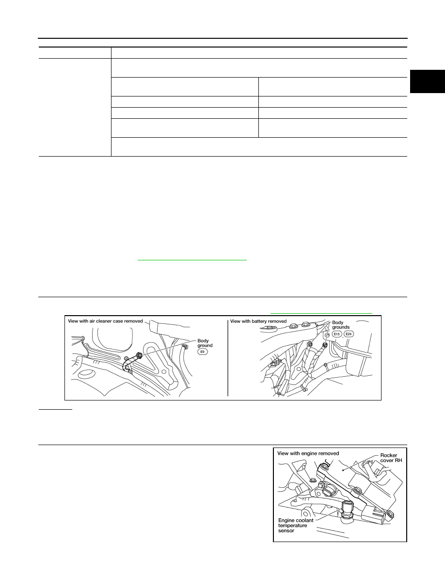
CHECK GROUND CONNECTIONS
1. Turn ignition switch OFF.
2. Loosen and retighten three ground screws on the body. Refer to
.
OK or NG
OK
>> GO TO 2.
NG
>> Repair or replace ground connections.
2.
CHECK ECT SENSOR POWER SUPPLY CIRCUIT
1. Disconnect engine coolant temperature (ECT) sensor harness
connector.
2. Turn ignition switch ON.
Detected items
Engine operating condition in fail-safe mode
Engine coolant temper-
ature sensor circuit
Engine coolant temperature will be determined by ECM based on the following condition.
CONSULT displays the engine coolant temperature decided by ECM.
Condition
Engine coolant temperature decided
(CONSULT display)
Just as ignition switch is turned ON or START
40
°C (104°F)
Approx. 4 minutes or more after engine starting
80
°C (176°F)
Except as shown above
40 - 80
°C (104 - 176°F)
(Depends on the time)
When the fail-safe system for engine coolant temperature sensor is activated, the cooling fan operates while
engine is running.
BBIA0539E
BBIA0542E