Nissan Frontier. Manual - part 606


  Index      Nissan     Nissan Frontier (2014 year) - Service and Repair Manual


Search            


Content   ..  604  605  606  607   ..


Nissan Frontier. Manual - part 606


VARIABLE INDUCTION AIR SYSTEM

EC-995

< SYSTEM DESCRIPTION >

[VQ40DE FOR MEXICO]

C

D

E

F

G

H

I

J

K

L

M

A

EC

N

P

O

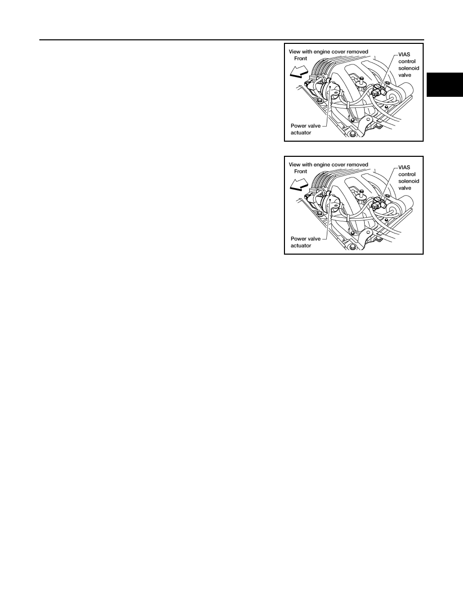
The power valve is installed in intake manifold collector and used to

control the suction passage of the variable induction air control sys-

tem. It is set in the fully closed or fully opened position by the power

valve actuator operated by the vacuum saved in the surge tank. The

vacuum in the surge tank is controlled by the VIAS control solenoid

valve.

VIAS Control Solenoid Valve

The VIAS control solenoid valve cuts the intake manifold vacuum

signal for power valve control. It responds to ON/OFF signals from

the ECM. When the solenoid is off, the vacuum signal from the

intake manifold is cut. When the ECM sends an ON signal the coil

pulls the plunger downward and feeds the vacuum signal to the

power valve actuator.

BBIA0569E

BBIA0569E

EC-996

< SYSTEM DESCRIPTION >

[VQ40DE FOR MEXICO]

VARIABLE INDUCTION AIR SYSTEM

Vacuum Hose Drawing

INFOID:0000000009481693

Refer to 

EC-971, "System Diagram"

 for Vacuum Control System.

PBIB2529E

ON BOARD DIAGNOSTIC (OBD) SYSTEM

EC-997

< SYSTEM DESCRIPTION >

[VQ40DE FOR MEXICO]

C

D

E

F

G

H

I

J

K

L

M

A

EC

N

P

O

ON BOARD DIAGNOSTIC (OBD) SYSTEM

Diagnosis Description

INFOID:0000000009481694

This system is an on board diagnostic system that records exhaust emission-related diagnostic information

and detects a sensors/actuator-related malfunction. A malfunction is indicated by the malfunction indicator

lamp (MIL) and stored in control module memory as a DTC. The diagnostic information can be obtained with

the diagnostic tool (GST: Generic Scan Tool).

GST (Generic Scan Tool)

INFOID:0000000009481695

When GST is connected with a data link connector equipped on the vehicle side, it will communicate with the

control module equipped in the vehicle and then enable various kinds of diagnostic tests. Refer to 

EC-997,

"Diagnosis Description"

.

NOTE:

Service $0A is not applied for regions where it is not mandated.

EC-998

< SYSTEM DESCRIPTION >

[VQ40DE FOR MEXICO]

DIAGNOSIS SYSTEM (ECM)

DIAGNOSIS SYSTEM (ECM)

DIAGNOSIS DESCRIPTION
DIAGNOSIS DESCRIPTION : 1st Trip Detection Logic and Two Trip Detection Logic

INFOID:0000000009481696

When a malfunction is detected for the first time, 1st trip DTC and 1st trip Freeze Frame data are stored in the

ECM memory. The MIL will not illuminate at this stage. <1st trip>

If the same malfunction is detected again during the next drive, the DTC and Freeze Frame data are stored in

the ECM memory, and the MIL illuminates. The MIL illuminates at the same time when the DTC is stored.

<2nd trip> The “trip” in the “Two Trip Detection Logic” means a driving mode in which self-diagnosis is per-

formed during vehicle operation. Specific on board diagnostic items will cause the ECM to illuminate or blink

the MIL, and store DTC and Freeze Frame data, even in the 1st trip, as shown below.

×: Applicable —: Not applicable

DIAGNOSIS DESCRIPTION : DTC and Freeze Frame Data

INFOID:0000000009481697

DTC AND 1ST TRIP DTC

The 1st trip DTC (whose number is the same as the DTC number) is displayed for the latest self-diagnostic

result obtained. If the ECM memory was cleared previously, and the 1st trip DTC did not recur, the 1st trip DTC

will not be displayed.

If a malfunction is detected during the 1st trip, the 1st trip DTC is saved in the ECM memory. The MIL will not

light up (two trip detection logic). If the same malfunction is not detected in the 2nd trip (meeting the required

driving pattern), the 1st trip DTC is cleared from the ECM memory. If the same malfunction is detected in the

2nd trip, both the 1st trip DTC and DTC are saved in the ECM memory and the MIL lights up. In other words,

the DTC is stored in the ECM memory and the MIL lights up when the same malfunction occurs in two consec-

utive trips. If a 1st trip DTC is stored and a non-diagnostic operation is performed between the 1st and 2nd

trips, only the 1st trip DTC will continue to be stored. For malfunctions that blink or light up the MIL during the

1st trip, the DTC and 1st trip DTC are stored in the ECM memory.

For malfunctions in which 1st trip DTCs are displayed, refer to 

EC-1031, "DTC Index"

. These items are

required by legal regulations to continuously monitor the system/component. In addition, the items monitored

non-continuously are also displayed on CONSULT.

1st trip DTC is specified in Service $07 of SAE J1979/ISO 15031-5. 1st trip DTC detection occurs without illu-

minating the MIL and therefore does not warn the driver of a malfunction.

When a 1st trip DTC is detected, check, print out or write down and erase (1st trip) DTC and Freeze Frame

data as specified in Work Flow procedure Step 2, refer to 

EC-1062, "Trouble Diagnosis Introduction"

. Then

perform DTC Confirmation Procedure or Component Function Check to try to duplicate the malfunction. If the

malfunction is duplicated, the item requires repair.

FREEZE FRAME DATA AND 1ST TRIP FREEZE FRAME DATA

The ECM records the driving conditions such as fuel system status, calculated load value, engine coolant tem-

perature, short term fuel trim, long term fuel trim, engine speed, vehicle speed, absolute throttle position, base

fuel schedule and intake air temperature at the moment a malfunction is detected.

Data which are stored in the ECM memory, along with the 1st trip DTC, are called 1st trip freeze frame data.

The data, stored together with the DTC data, are called freeze frame data and displayed on CONSULT or

GST. The 1st trip freeze frame data can only be displayed on the CONSULT screen.

Items

MIL

DTC

1st trip DTC

1st trip

2nd trip 

1st trip 

displaying

2nd trip 

displaying

1st trip 

displaying

2nd trip 

display-

ing

Blinking

Illuminat-

ed

Blinking

Illuminat-

ed

Misfire (Possible three way catalyst 
damage) — DTC: P0300 – P0306 
is being detected

×

×

Misfire (Possible three way catalyst 
damage) — DTC: P0300 – P0306 
is being detected

×

×

One trip detection diagnoses (Re-
fer to 

EC-1031, "DTC Index"

.)

×

×

Except above

×

×

×


Content   ..  604  605  606  607   ..