Nissan Frontier. Manual - part 565


  Index      Nissan     Nissan Frontier (2014 year) - Service and Repair Manual


Search            


Content   ..  563  564  565  566   ..


Nissan Frontier. Manual - part 565


P0643 SENSOR POWER SUPPLY

EC-831

< DTC/CIRCUIT DIAGNOSIS >

[VQ40DE FOR USA AND CANADA]

C

D

E

F

G

H

I

J

K

L

M

A

EC

N

P

O

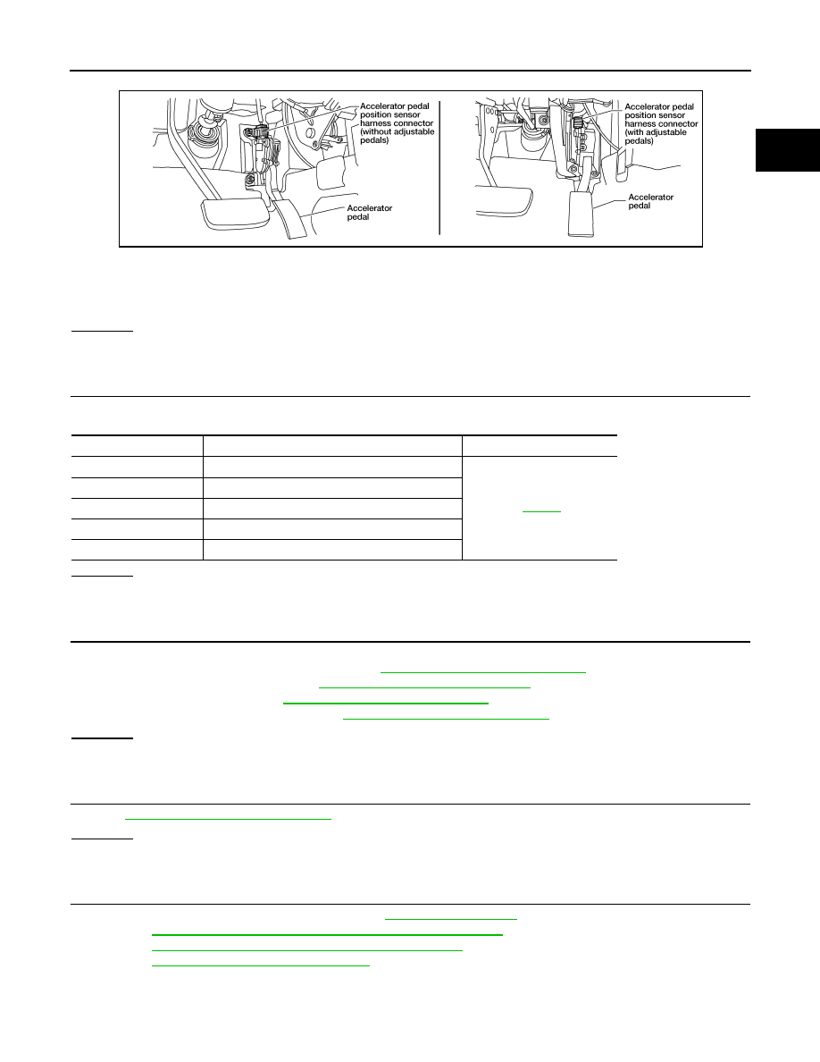
1. Disconnect accelerator pedal position (APP) sensor harness connector.

2. Turn ignition switch ON.

3. Check voltage between APP sensor terminal 2 and ground with CONSULT or tester.

OK or NG

OK

>> GO TO 5.

NG

>> GO TO 3.

3.

CHECK SENSOR POWER SUPPLY CIRCUITS

Check harness for short to power and short to ground, between the following terminals.

OK or NG

OK

>> GO TO 4.

NG

>> Repair short to ground or short to power in harness or connectors.

4.

CHECK COMPONENTS

Check the following.

• EVAP control system pressure sensor (Refer to 

EC-783, "Component Inspection"

.)

• Refrigerant pressure sensor (Refer to 

EC-947, "Component Description"

.)

• Battery current sensor (Refer to 

EC-849, "Component Inspection"

.)

• Power steering pressure sensor (Refer to 

EC-823, "Component Inspection"

.)

OK or NG

OK

>> GO TO 5.

NG

>> Replace malfunctioning component.

5.

CHECK APP SENSOR

Refer to 

EC-903, "Component Inspection"

.

OK or NG

OK

>> GO TO 7.

NG

>> GO TO 6.

6.

REPLACE ACCELERATOR PEDAL ASSEMBLY

1. Replace accelerator pedal assembly. Refer to 

ACC-3, "Component"

.

2. Perform 

EC-590, "Accelerator Pedal Released Position Learning"

.

3. Perform 

EC-591, "Throttle Valve Closed Position Learning"

.

4. Perform 

EC-591, "Idle Air Volume Learning"

.

>> INSPECTION END

Voltage: Approximately 5V

BBIA0556E

ECM terminal

Sensor terminal

Reference Wiring Diagram

107

EVAP control system pressure sensor terminal 3

EC-556

96

Refrigerant pressure sensor terminal 3

75

Battery current sensor terminal 1

79

PSP sensor terminal 3

99

APP sensor terminal 2

EC-832

< DTC/CIRCUIT DIAGNOSIS >

[VQ40DE FOR USA AND CANADA]

P0643 SENSOR POWER SUPPLY

7.

CHECK INTERMITTENT INCIDENT

Refer to 

GI-42, "Intermittent Incident"

.

>> INSPECTION END

P0850 PNP SWITCH

EC-833

< DTC/CIRCUIT DIAGNOSIS >

[VQ40DE FOR USA AND CANADA]

C

D

E

F

G

H

I

J

K

L

M

A

EC

N

P

O

P0850 PNP SWITCH

Component Description

INFOID:0000000009481511

When the shift lever position is Neutral, park/neutral position (PNP) switch is ON. (M/T)

When the selector lever position is P or N, park/neutral position (PNP) signal is sent to ECM from TCM via

combination meter (unified meter control unit). (A/T)

ECM detects the position because the continuity of the line (the ON signal) exists.

On Board Diagnosis Logic

INFOID:0000000009481512

DTC Confirmation Procedure

INFOID:0000000009481513

CAUTION:

Always drive vehicle at a safe speed.

NOTE:

If DTC Confirmation Procedure has been previously conducted, always perform the following before conduct-

ing the next step.

1. Turn ignition switch OFF and wait at least 10 seconds.

2. Turn ignition switch ON.

3. Turn ignition switch OFF and wait at least 10 seconds.

 WITH CONSULT

1. Turn ignition switch ON.

2. Select “P/N POSI SW” in “DATA MONITOR” mode with CONSULT. Then check the “P/N POSI SW” signal

under the following conditions.

If NG, go to 

EC-834, "Diagnosis Procedure"

.

If OK, go to following step.

3. Select “DATA MONITOR” mode with CONSULT.

4. Start engine and warm it up to normal operating temperature.

5. Maintain the following conditions for at least 60 consecutive seconds.

6. Check 1st trip DTC.

7. If 1st trip DTC is detected, go to 

EC-834, "Diagnosis Procedure"

.

DTC No.

Trouble diagnosis name

DTC detecting condition

Possible cause

P0850
0850

Park/neutral position 
switch

The park/neutral position (PNP) signal not 
change during driving after the engine in start-
ed.

• Harness or connectors

[The park/neutral position (PNP) signal 
circuit is open or shorted.]

• Park/neutral position (PNP) switch (M/T)
• Transmission range switch (A/T)
• Combination meter
• TCM (A/T)

Position (Selector lever)

Known-good signal

P or N position (A/T)
Neutral position (M/T)

ON

Except above position

OFF

ENG SPEED

1,400 - 6,375 rpm

COOLAN TEMP/S

More than 70

°C (158°F)

B/FUEL SCHDL

2.0 - 31.8 msec

VHCL SPEED SE

More than 64 km/h (40 MPH)

Selector lever

Suitable position

EC-834

< DTC/CIRCUIT DIAGNOSIS >

[VQ40DE FOR USA AND CANADA]

P0850 PNP SWITCH

Overall Function Check

INFOID:0000000009481514

Use this procedure to check the overall function of the park/neutral position (PNP) signal circuit. During this

check, a 1st trip DTC might not be confirmed.

 WITH GST

1. Turn ignition switch ON.

2. Check voltage between ECM terminal 117 (PNP signal) and ground under the following conditions.

3. If NG, go to 

EC-834, "Diagnosis Procedure"

.

Diagnosis Procedure

INFOID:0000000009481515

A/T MODELS

1.

CHECK DTC WITH TCM

Refer to 

TM-231, "DTC No. Index"

.

OK or NG

OK

>> GO TO 2.

NG

>> Repair or replace.

2.

CHECK STARTING SYSTEM

Turn ignition switch OFF, then turn it to START.

Does starter motor operate?
Yes or No

Yes

>> GO TO 3.

No

>> Refer to 

STR-6, "Work Flow (With GR8-1200 NI)"

 or 

STR-10, "Work Flow (Without GR8-1200

NI)"

.

3.

CHECK PNP INPUT SIGNAL CIRCUIT FOR OPEN AND SHORT-I

1. Turn ignition switch OFF.

2. Disconnect A/T assembly harness connector.

3. Disconnect combination meter harness connector.

4. Check harness continuity between A/T assembly terminal 9 and combination meter terminal 17.

Refer to Wiring Diagram.

5. Also check harness for short to ground and short to power.
OK or NG

OK

>> GO TO 5.

NG

>> GO TO 4.

4.

DETECT MALFUNCTIONING PART

Check the following.

• Harness connectors M31, E152

• Harness connectors E5, F14

• Harness for open or short between A/T assembly and combination meter.

>> Repair open circuit or short to ground or short to power in harness or connectors.

5.

CHECK PNP INPUT SIGNAL CIRCUIT FOR OPEN AND SHORT-II

1. Disconnect ECM harness connector.

Condition (Gear position)

Voltage V (Known-good data)

P or N position (A/T)
Neutral position (M/T)

Approx. 0

Except above position

BATTERY VOLTAGE

(11 - 14V)

Continuity should exist.


Content   ..  563  564  565  566   ..