Nissan Frontier. Manual - part 462
P2122, P2123 APP SENSOR
EC-419
< DTC/CIRCUIT DIAGNOSIS >
[QR25DE]
C
D
E
F
G
H
I
J
K
L
M
A
EC
N
P
O
Diagnosis Procedure
INFOID:0000000009481125
1.
CHECK GROUND CONNECTIONS
1. Turn ignition switch OFF.
2. Loosen and retighten two ground screws on the body. Refer to
.
OK or NG
OK
>> GO TO 2.
NG
>> Repair or replace ground connections.
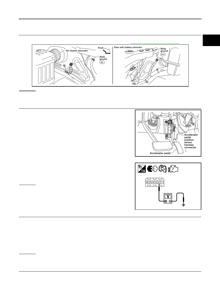
2.
CHECK APP SENSOR 1 POWER SUPPLY CIRCUIT
1. Disconnect accelerator pedal position (APP) sensor harness
connector.
2. Turn ignition switch ON.
3. Check voltage between APP sensor terminal 2 and ground with
CONSULT or tester.
OK or NG
OK
>> GO TO 3.
NG
>> Repair open circuit, short to ground or short to power in
harness or connectors.
3.
CHECK APP SENSOR 1 GROUND CIRCUIT FOR OPEN AND SHORT
1. Turn ignition switch OFF.
2. Disconnect ECM harness connector.
3. Check harness continuity between APP sensor terminal 4 and ECM terminal 84.
Refer to Wiring Diagram.
4. Also check harness for short to ground and short to power.
OK or NG
OK
>> GO TO 4.
NG
>> Repair open circuit, short to ground or short to power in harness or connectors.
4.
CHECK APP SENSOR 1 INPUT SIGNAL CIRCUIT FOR OPEN AND SHORT
BBIA0614E
BBIA0592E
Voltage: Approximately 5V
PBIB2608E
Continuity should exist.