Nissan Frontier. Manual - part 451
P1551, P1552 BATTERY CURRENT SENSOR
EC-375
< DTC/CIRCUIT DIAGNOSIS >
[QR25DE]
C
D
E
F
G
H
I
J
K
L
M
A
EC
N
P
O
P1551, P1552 BATTERY CURRENT SENSOR
Component Description
INFOID:0000000009481063
The power generation voltage variable control enables fuel con-
sumption to be decreased by reducing the engine load which is
caused by the power generation of the generator. The battery cur-
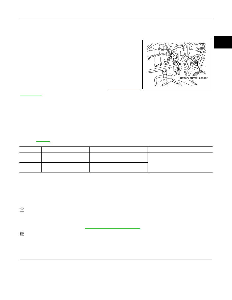
rent sensor is installed to the battery cable at the negative terminal.
The sensor measures the charging/discharging current of the bat-
tery. Based on the sensor signal, ECM judges whether or not the
power generation voltage variable control is performed. When per-
forming the power generation voltage variable control, ECM calcu-
lates the target power generation voltage based on the sensor
signal. And ECM sends the calculated value as the power genera-
tion command value to IPDM E/R. For the details of the power gen-
eration voltage variable control, refer to
.
CAUTION:
Never connect the electrical component or the ground wire directly to the battery terminal. The con-
nection causes the malfunction of the power generation voltage variable control, and then the battery
discharge may occur.
On Board Diagnosis Logic
INFOID:0000000009481064
The MIL will not light up for these diagnosis.
NOTE:
If DTC P1551 or P1552 is displayed with DTC P0643, first perform the trouble diagnosis for DTC P0643.
Refer to
.
DTC Confirmation Procedure
INFOID:0000000009481065
If DTC Confirmation Procedure has been previously conducted, always turn ignition switch OFF and wait at
least 10 seconds before conducting the next test.
TESTING CONDITION:
Before performing the following procedure, confirm that battery voltage is more than 10V with ignition
switch ON
WITH CONSULT
1. Turn ignition switch ON and wait at least 10 seconds.
2. Check 1st trip DTC.
3. If 1st trip DTC is detected, go to
WITH GST
Follow the procedure “WITH CONSULT” above.
Diagnosis Procedure
INFOID:0000000009481066
1.
CHECK GROUND CONNECTIONS
1. Turn ignition switch OFF.
2. Loosen and retighten two ground screws on the body.
BBIA0630E
DTC No.
Trouble diagnosis name
DTC detecting condition
Possible cause
P1551
1551
Battery current sensor circuit
low input
An excessively low voltage from the
sensor is sent to ECM.
• Harness or connectors
(The sensor circuit is open or shorted.)
• Battery current sensor
P1552
1552
Battery current sensor circuit
high input
An excessively high voltage from the
sensor is sent to ECM.