Nissan Frontier. Manual - part 449


  Index      Nissan     Nissan Frontier (2014 year) - Service and Repair Manual


Search            


Content   ..  447  448  449  450   ..


Nissan Frontier. Manual - part 449


P1217 ENGINE OVER TEMPERATURE

EC-367

< DTC/CIRCUIT DIAGNOSIS >

[QR25DE]

C

D

E

F

G

H

I

J

K

L

M

A

EC

N

P

O

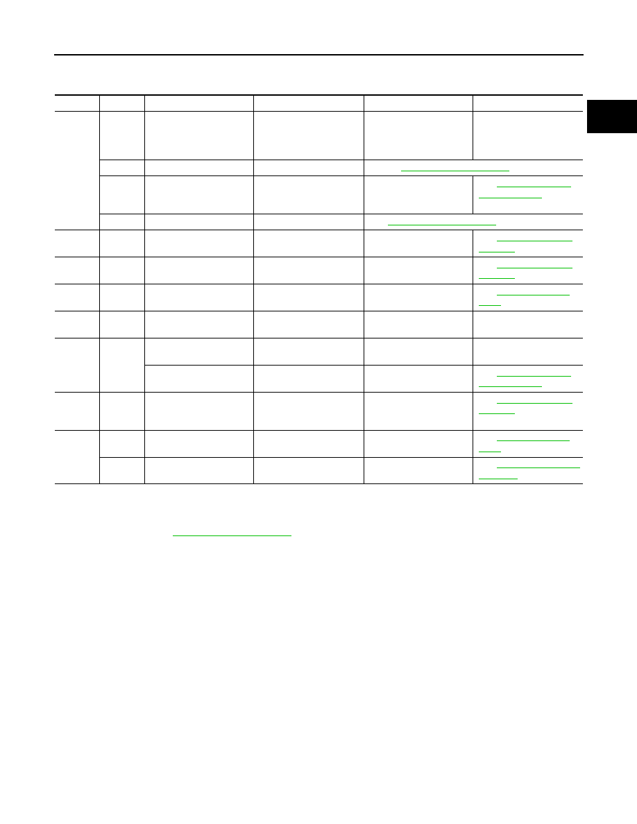
Main 12 Causes of Overheating

INFOID:0000000009481049

*1: Engine running at 3,000 rpm for 10 minutes.
*2: Drive at 90 km/h (55 MPH) for 30 minutes and then let idle for 10 minutes.
*3: After 60 minutes of cool down time.
For more information, refer to 

CO-9, "Troubleshooting Chart"

.

Engine

 Step

Inspection item

Equipment

 Standard

Reference page

OFF

1

• Blocked radiator
• Blocked condenser
• Blocked radiator grille
• Blocked bumper

• Visual

No blocking

2

• Coolant mixture

• Coolant tester

Refer to

CO-11, "System Inspection"

3

• Coolant level

• Visual

Coolant up to MAX level 
in reservoir tank and radi-
ator filler neck

See 

CO-12, "Changing 

Engine Coolant"

.

4

• Radiator cap

• Pressure tester

See 

CO-11, "System Inspection"

.

ON*

1

5

• Coolant leaks 

• Visual

No leaks

See 

CO-11, "System In-

spection"

.

ON*

1

6

• Thermostat

• Touch the upper and 

lower radiator hoses

Both hoses should be hot See 

CO-11, "System In-

spection"

.

ON*

1

7

• Cooling fan

• Visual

Operating

See 

CO-19, "Exploded 

View"

.

OFF

8

• Combustion gas leak

• Color checker chemical 

tester 4 Gas analyzer

Negative

ON*

2

9

• Coolant temperature 

gauge

• Visual

Gauge less than 3/4 when 
driving

• Coolant overflow to res-

ervoir tank

• Visual

No overflow during driving 
and idling

See 

CO-12, "Changing 

Engine Coolant"

.

OFF*

3

10

• Coolant return from 

reservoir tank to radia-
tor

• Visual

Should be initial level in 
reservoir tank

See 

CO-11, "System In-

spection"

.

OFF

11

• Cylinder head

• Straight gauge feeler 

gauge

0.1 mm (0.004 in) Maxi-
mum distortion (warping)

See 

EM-67, "Exploded 

View"

.

12

• Cylinder block and pis-

tons

• Visual

No scuffing on cylinder 
walls or piston

See 

CO-9, "Troubleshoot-

ing Chart"

.

EC-368

< DTC/CIRCUIT DIAGNOSIS >

[QR25DE]

P1225 TP SENSOR

P1225 TP SENSOR

Component Description

INFOID:0000000009481050

Electric throttle control actuator consists of throttle control motor,

throttle position sensor, etc. The throttle position sensor responds to

the throttle valve movement. 

The throttle position sensor has two sensors. These sensors are a

kind of potentiometers which transform the throttle valve position into

output voltage, and emit the voltage signal to the ECM. In addition,

these sensors detect the opening and closing speed of the throttle

valve and feed the voltage signals to the ECM. The ECM judges the

current opening angle of the throttle valve from these signals and the

ECM controls the throttle control motor to make the throttle valve

opening angle properly in response to driving condition.

On Board Diagnosis Logic

INFOID:0000000009481051

The MIL will not light up for this self-diagnosis.

DTC Confirmation Procedure

INFOID:0000000009481052

NOTE:

If DTC Confirmation Procedure has been previously conducted, always turn ignition switch OFF and wait at

least 10 seconds before conducting the next test.

TESTING CONDITION:

Before performing the following procedure, confirm that battery voltage is more than 10V at idle.

 WITH CONSULT

1. Turn ignition switch OFF and wait at least 10 seconds.
2. Turn ignition switch ON.
3. Check 1st trip DTC.
4. If 1st trip DTC is detected, go to 

EC-368, "Diagnosis Procedure"

.

 WITH GST

Follow the procedure “With CONSULT” above.

Diagnosis Procedure

INFOID:0000000009481053

1.

CHECK ELECTRIC THROTTLE CONTROL ACTUATOR VISUALLY

1. Turn ignition switch OFF.

2. Remove the intake air duct.

3. Check if foreign matter is caught between the throttle valve and

the housing.

OK or NG

OK

>> GO TO 2.

NG

>> Remove the foreign matter and clean the electric throttle

control actuator inside, and then perform throttle valve

closed position learning. Refer to 

EC-123, "Throttle

Valve Closed Position Learning"

.

2.

REPLACE ELECTRIC THROTTLE CONTROL ACTUATOR

PBIB0145E

DTC No.

Trouble diagnosis name

DTC detecting condition

Possible cause

P1225
1225

Closed throttle position learning 
performance problem

Closed throttle position learning value is 
excessively low.

• Electric throttle control actuator

(TP sensor 1 and 2)

BBIA0623E

P1225 TP SENSOR

EC-369

< DTC/CIRCUIT DIAGNOSIS >

[QR25DE]

C

D

E

F

G

H

I

J

K

L

M

A

EC

N

P

O

1. Replace the electric throttle control actuator. Refer to 

EM-27, "Exploded View"

.

2. Perform 

EC-123, "Throttle Valve Closed Position Learning"

.

3. Perform 

EC-124, "Idle Air Volume Learning"

.

>> INSPECTION END

EC-370

< DTC/CIRCUIT DIAGNOSIS >

[QR25DE]

P1226 TP SENSOR

P1226 TP SENSOR

Component Description

INFOID:0000000009481054

Electric throttle control actuator consists of throttle control motor,

throttle position sensor, etc. The throttle position sensor responds to

the throttle valve movement. 

The throttle position sensor has two sensors. These sensors are a

kind of potentiometers which transform the throttle valve position into

output voltage, and emit the voltage signal to the ECM. In addition,

these sensors detect the opening and closing speed of the throttle

valve and feed the voltage signals to the ECM. The ECM judges the

current opening angle of the throttle valve from these signals and the

ECM controls the throttle control motor to make the throttle valve

opening angle properly in response to driving condition.

On Board Diagnosis Logic

INFOID:0000000009481055

The MIL will not light up for this self-diagnosis.

DTC Confirmation Procedure

INFOID:0000000009481056

NOTE:

If DTC Confirmation Procedure has been previously conducted, always turn ignition switch OFF and wait at

least 10 seconds before conducting the next test.

TESTING CONDITION:

Before performing the following procedure, confirm that battery voltage is more than 10V at idle.

 WITH CONSULT

1. Turn ignition switch OFF and wait at least 10 seconds.
2. Turn ignition switch ON.
3. Repeat steps 1 and 2 for 32 times.
4. Check 1st trip DTC.
5. If 1st trip DTC is detected, go to 

EC-370, "Diagnosis Procedure"

.

 WITH GST

Follow the procedure “With CONSULT” above.

Diagnosis Procedure

INFOID:0000000009481057

1.

CHECK ELECTRIC THROTTLE CONTROL ACTUATOR VISUALLY

1. Turn ignition switch OFF.

2. Remove the intake air duct.

3. Check if foreign matter is caught between the throttle valve and

the housing.

OK or NG

OK

>> GO TO 2.

NG

>> Remove the foreign matter and clean the electric throttle

control actuator inside, and then perform throttle valve

closed position learning. Refer to 

EC-123, "Throttle

Valve Closed Position Learning"

.

PBIB0145E

DTC No.

Trouble diagnosis name

DTC detecting condition

Possible cause

P1226
1226

Closed throttle position learning 
performance problem

Closed throttle position learning is not performed 
successfully, repeatedly.

• Electric throttle control actuator

(TP sensor 1 and 2)

BBIA0623E


Content   ..  447  448  449  450   ..