Nissan Frontier. Manual - part 422


  Index      Nissan     Nissan Frontier (2014 year) - Service and Repair Manual


Search            


Content   ..  420  421  422  423   ..


Nissan Frontier. Manual - part 422


P0335 CKP SENSOR (POS)

EC-259

< DTC/CIRCUIT DIAGNOSIS >

[QR25DE]

C

D

E

F

G

H

I

J

K

L

M

A

EC

N

P

O

 WITH GST

Follow the procedure “WITH CONSULT” above.

Diagnosis Procedure

INFOID:0000000009480919

1.

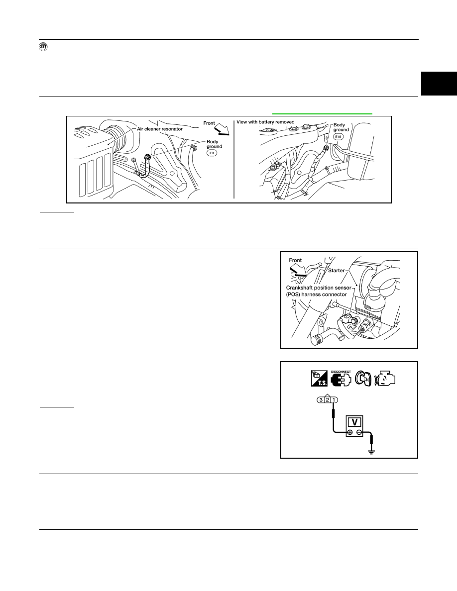
CHECK GROUND CONNECTIONS

1. Turn ignition switch OFF.

2. Loosen and retighten two ground screws on the body. Refer to 

EC-149, "Ground Inspection"

.

OK or NG

OK

>> GO TO 2.

NG

>> Repair or replace ground connections.

2.

CHECK CRANKSHAFT POSITION (CKP) SENSOR (POS) POWER SUPPLY CIRCUIT

1. Disconnect crankshaft position (CKP) sensor (POS) harness

connector.

2. Turn ignition switch ON.

3. Check voltage between CKP sensor (POS) terminal 1 and

ground with CONSULT or tester.

OK or NG

OK

>> GO TO 4.

NG

>> GO TO 3.

3.

DETECT MALFUNCTIONING PART

Check the following.

• Harness for open or short between crankshaft position sensor (POS) and ECM

>> Repair open circuit, short to ground or short to power in harness or connectors.

4.

CHECK CKP (POS) GROUND CIRCUIT FOR OPEN AND SHORT

1. Turn ignition switch OFF.

2. Check harness continuity between CKP sensor (POS) terminal 3 and ground. 

Refer to Wiring Diagram.

BBIA0614E

BBIA0619E

Voltage: Approximately 5 V

PBIB0664E

EC-260

< DTC/CIRCUIT DIAGNOSIS >

[QR25DE]

P0335 CKP SENSOR (POS)

3. Also check harness for short to power.
OK or NG

OK

>> GO TO 6.

NG

>> GO TO 5.

5.

DETECT MALFUNCTIONING PART

Check the following.

• Harness for open or short between crankshaft position sensor (POS) and ECM.

>> Repair open circuit or short to power in harness or connectors.

6.

CHECK CKP SENSOR (POS) INPUT SIGNAL CIRCUIT FOR OPEN AND SHORT

1. Disconnect ECM harness connector.

2. Check harness continuity between ECM terminal 65 and CKP sensor (POS) terminal 2.

Refer to Wiring Diagram.

3. Also check harness for short to ground and short to power.
OK or NG

OK

>> GO TO 7.

NG

>> Repair open circuit, short to ground or short to power in harness or connectors.

7.

CHECK CRANKSHAFT POSITION SENSOR (POS)

Refer to 

EC-260, "Component Inspection"

.

OK or NG

OK

>> GO TO 8.

NG

>> Replace crankshaft position sensor (POS). Refer to 

EM-80, "Exploded View"

.

8.

CHECK GEAR TOOTH

Visually check for chipping signal plate gear tooth.
OK or NG

OK

>> GO TO 9.

NG

>> Replace the signal plate.

9.

CHECK INTERMITTENT INCIDENT

Refer to 

GI-42, "Intermittent Incident"

.

>> INSPECTION END

Component Inspection

INFOID:0000000009480920

CRANKSHAFT POSITION SENSOR (POS)

1. Loosen the fixing bolt of the sensor.
2. Disconnect crankshaft position sensor (POS) harness connector.
3. Remove the sensor.

Continuity should exist.

Continuity should exist.

P0335 CKP SENSOR (POS)

EC-261

< DTC/CIRCUIT DIAGNOSIS >

[QR25DE]

C

D

E

F

G

H

I

J

K

L

M

A

EC

N

P

O

4. Visually check the sensor for chipping.

5. Check resistance as shown in the figure.

6. If NG, replace crankshaft position sensor (POS).

PBIB0563E

Terminal No. (Polarity)

Resistance 

Ω [at 25°C (77°F)]

1 (+) - 2 (-)

Except 0 or 

1 (+) - 3 (-)

2 (+) - 3 (-)

PBIB0564E

EC-262

< DTC/CIRCUIT DIAGNOSIS >

[QR25DE]

P0340 CMP SENSOR (PHASE)

P0340 CMP SENSOR (PHASE)

Component Description

INFOID:0000000009480921

The camshaft position sensor (PHASE) senses the retraction with

camshaft (intake) to identify a particular cylinder. The camshaft posi-

tion sensor (PHASE) senses the piston position.

When the crankshaft position sensor (POS) system becomes inoper-

ative, the camshaft position sensor (PHASE) provides various con-

trols of engine parts instead, utilizing timing of cylinder identification

signals.

The sensor consists of a permanent magnet and Hall IC.

When engine is running, the high and low parts of the teeth cause

the gap with the sensor to change.

The changing gap causes the magnetic field near the sensor to

change.

Due to the changing magnetic field, the voltage from the sensor changes. 

ECM receives the signals as shown in the figure.

On Board Diagnosis Logic

INFOID:0000000009480922

DTC Confirmation Procedure

INFOID:0000000009480923

NOTE:

If DTC Confirmation Procedure has been previously conducted, always turn ignition switch OFF and wait at

least 10 seconds before conducting the next test.

TESTING CONDITION:

Before performing the following procedure, confirm that battery voltage is more than 10.5V with igni-

tion switch ON.

 WITH CONSULT

1. Crank engine for at least 2 seconds and run it for at least 5 seconds at idle speed.
2. Check 1st trip DTC.
3. If 1st trip DTC is detected, go to 

EC-263, "Diagnosis Procedure"

.

If 1st trip DTC is not detected, go to next step.

4. Maintaining engine speed at more than 800 rpm for at least 5 seconds.
5. Check 1st trip DTC.
6. If 1st trip DTC is detected, go to 

EC-263, "Diagnosis Procedure"

.

PBIB0562E

PBIB2382E

DTC No.

Trouble diagnosis name

DTC detecting condition

Possible cause

P0340
0340

Camshaft position sen-
sor (PHASE) circuit

• The cylinder No. signal is not sent to ECM for 

the first few seconds during engine cranking.

• The cylinder No. signal is not set to ECM dur-

ing engine running.

• The cylinder No. signal is not in the normal 

pattern during engine running.

• Harness or connectors

(The sensor circuit is open or shorted)

• Camshaft position sensor (PHASE)
• Camshaft (Intake)
• Starter motor (Refer to 

STR-35, "Remov-

al and Installation (QR25DE)"

.)

• Starting system circuit (Refer to 

STR-12, 

"A/T : System Diagram"

.)

• Dead (Weak) battery


Content   ..  420  421  422  423   ..