Nissan Frontier. Manual - part 420


  Index      Nissan     Nissan Frontier (2014 year) - Service and Repair Manual


Search            


Content   ..  418  419  420  421   ..


Nissan Frontier. Manual - part 420


P0300, P0301, P0302, P0303, P0304 MISFIRE

EC-251

< DTC/CIRCUIT DIAGNOSIS >

[QR25DE]

C

D

E

F

G

H

I

J

K

L

M

A

EC

N

P

O

When disconnecting each fuel injector harness connector one at a

time, is there any cylinder which does not produce a momentary

engine speed drop?

Yes or No

Yes

>> GO TO 4.

No

>> GO TO 9.

4.

CHECK FUNCTION OF FUEL INJECTOR

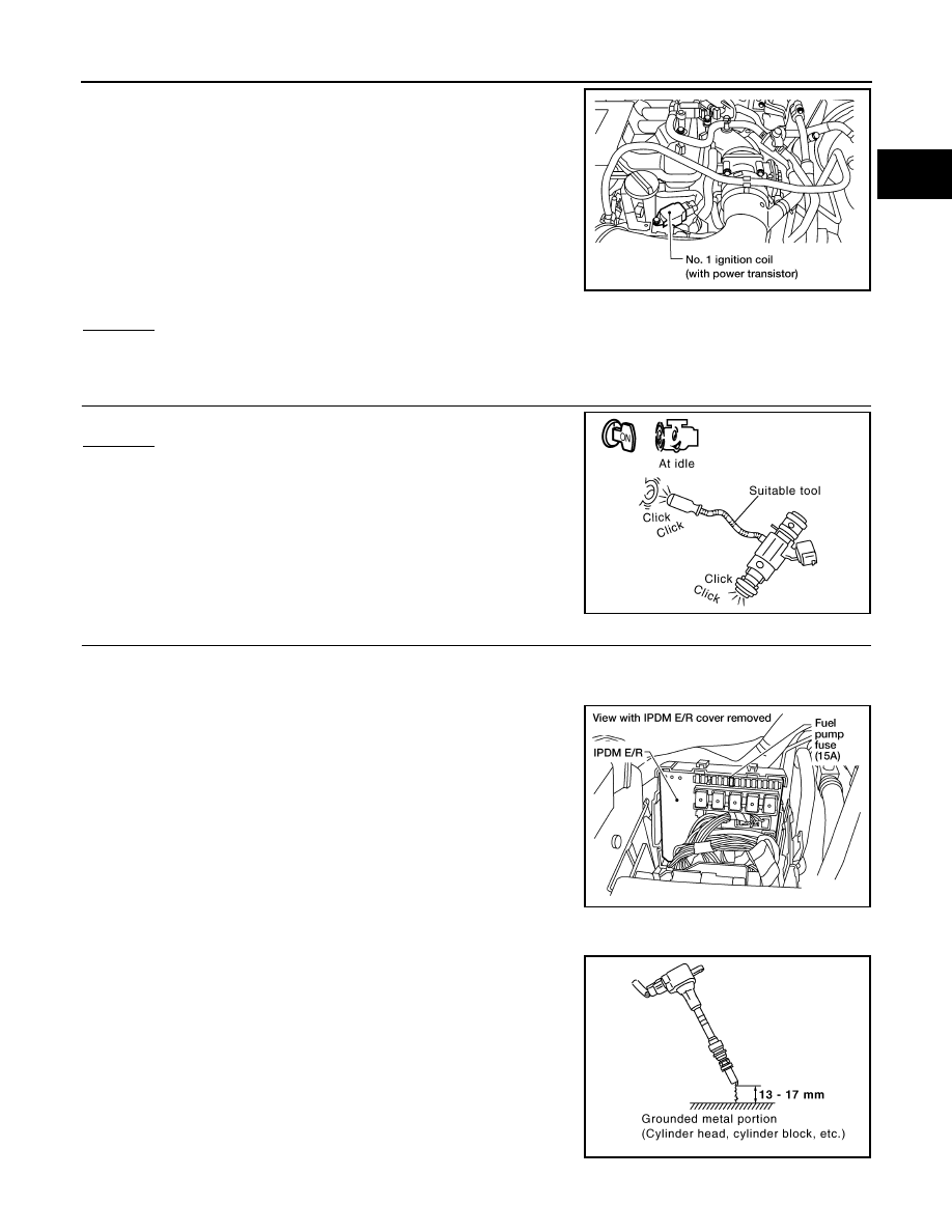
Does each fuel injector make an operating sound at idle?
Yes or No

Yes

>> GO TO 5.

No

>> Check fuel injector(s) and circuit(s). 

5.

CHECK FUNCTION OF IGNITION COIL-I

CAUTION:

Never the following procedure in a place with no combusyible objects and good ventilation.

1. Turn ignition switch OFF.

2. Remove fuel pump fuse in IPDM E/R to release fuel pressure.

NOTE:

Do not use CONSULT to release fuel pressure, or fuel pressure

applies again during the following procedure.

3. Start engine.

4. After engine stalls, crank it two or three times to release all fuel

pressure.

5. Turn ignition switch OFF.

6. Remove all ignition coil harness connectors to avoid the electri-

cal discharge from the ignition coils.

7. Remove ignition coil and spark plug of the cylinder to be

checked.

8. Crank engine for 5 seconds or more to remove combustion gas in the cylinder.

9. Connect spark plug and harness connector to ignition coil.

10. Fix ignition coil using a rope etc. with gap of 13 - 17 mm

between the edge of the spark plug and grounded metal portion

as shown in the figure.

11. Crank engine for about three seconds, and check whether spark

is generated between the spark plug and the grounded metal

portion.

CAUTION:

BBIA0604E

PBIB1986E

Spark should be generated.

BBIA0534E

PBIB2325E

EC-252

< DTC/CIRCUIT DIAGNOSIS >

[QR25DE]

P0300, P0301, P0302, P0303, P0304 MISFIRE

• Never place the spark plug and the ignition coil within 50 cm (19.7 in) each other. Be careful not

to get an electrical shock while checking, because the electrical discharge voltage becomes 20

kV or more.

• It might damage the ignition coil if the gap of more than 17 mm is made.

NOTE:

When the gap is less than 13 mm, a spark might be generated even if the coil is malfunctioning.

OK or NG

OK

>> GO TO 9.

NG

>> GO TO 6.

6.

CHECK FUNCTION OF IGNITION COIL-II

1. Turn ignition switch OFF.

2. Disconnect spark plug and connect a non-malfunctioning spark plug.

3. Crank engine for about 3 seconds, and recheck whether spark is generated between the spark plug and

the grounded metal portion.

OK or NG

OK

>> GO TO 7.

NG

>> Check ignition coil, power transistor and their circuits. 

7.

CHECK SPARK PLUG

Check the initial spark plug for fouling, etc.
OK or NG

OK

>> Replace spark plug(s) with standard type one(s). Refer

to 

EM-36, "Removal and Installation"

.

NG

>> 1. Repair or clean spark plug.

2. GO TO 8.

8.

CHECK FUNCTION OF IGNITION COIL-III

1. Reconnect the initial spark plugs.

2. Crank engine for about 3 seconds, and recheck whether spark is generated between the spark plug and

the grounded portion.

OK or NG

OK

>> INSPECTION END

NG

>> Replace spark plug(s) with standard type one(s). For spark plug type. Refer to 

EM-36, "Removal

and Installation"

.

9.

CHECK COMPRESSION PRESSURE

Check compression pressure.

Refer to 

EM-23, "Compression Pressure"

.

OK or NG

OK

>> GO TO 10.

NG

>> Check pistons, piston rings, valves, valve seats and cylinder head gaskets.

10.

CHECK FUEL PRESSURE

1. Install all removed parts.

2. Release fuel pressure to zero. Refer to 

EC-466, "Fuel Pressure Check"

.

3. Install fuel pressure gauge kit [SST (J-44321)] and check fuel pressure. Refer to 

EC-466, "Fuel Pressure

Check"

.

Spark should be generated.

SEF156I

Spark should be generated.

P0300, P0301, P0302, P0303, P0304 MISFIRE

EC-253

< DTC/CIRCUIT DIAGNOSIS >

[QR25DE]

C

D

E

F

G

H

I

J

K

L

M

A

EC

N

P

O

OK or NG

OK

>> GO TO 12.

NG

>> GO TO 11.

11.

DETECT MALFUNCTIONING PART

Check the following.

• Fuel pump and circuit.

• Fuel pressure regulator (Refer to 

EC-466, "Fuel Pressure Check"

.)

• Fuel lines

• Fuel filter for clogging

>> Repair or replace.

12.

CHECK IGNITION TIMING

Check the following items. Refer to 

EC-117, "Basic Inspection"

.

OK or NG

OK

>> GO TO 13.

NG

>> Follow the 

EC-117, "Basic Inspection"

13.

CHECK A/F SENSOR 1 INPUT SIGNAL CIRCUIT

1. Turn ignition switch OFF.

2. Disconnect ECM harness connector and A/F sensor 1 harness

connector.

3. Check harness continuity between the following terminals. Refer

to Wiring Diagram.

4. Check harness continuity between ECM terminals 45, 49 or A/F sensor 1 terminals 1, 2 and ground. Refer

to Wiring Diagram.

5. Also check harness for short to power.
OK or NG

OK

>> GO TO 14.

NG

>> Repair open circuit, short to ground or short to power in harness or connectors.

14.

CHECK A/F SENSOR 1 HEATER

Refer to 

EC-157, "Component Inspection"

.

OK or NG

OK

>> GO TO 15.

NG

>> Replace A/F sensor 1. Refer to 

EM-31, "Exploded View"

.

At idle: Approximately 350 kPa (3.57 kg/cm

2

, 51 psi)

Items

Specifications

Target idle speed

A/T: 700 

± 50 rpm (in P or N position)

M/T: 625 

± 50 rpm (in Neutral position)

Ignition timing

A/T: 15 

± 5° BTDC (in P or N position)

M/T: 15 

± 5° BTDC (in Neutral position)

A/F sensor 1 terminal

ECM terminal

1

45

2

49

Continuity should exist.

Continuity should not exist.

BBIA0617E

EC-254

< DTC/CIRCUIT DIAGNOSIS >

[QR25DE]

P0300, P0301, P0302, P0303, P0304 MISFIRE

15.

CHECK MASS AIR FLOW SENSOR

With CONSULT

Check “MASS AIR FLOW” in “DATA MONITOR” mode with CONSULT.

With GST

Check mass air flow sensor signal in SERVICE $01 with GST.

OK or NG

OK

>> GO TO 16.

NG

>> Check connectors for rusted terminals or loose connections in the mass air flow sensor circuit or

grounds.Refer to 

EC-164

.

16.

CHECK SYMPTOM MATRIX CHART

Check items on the rough idle symptom in 

EC-461, "Symptom Matrix Chart"

.

OK or NG

OK

>> GO TO 17.

NG

>> Repair or replace.

17.

ERASE THE 1ST TRIP DTC

Some tests may cause a 1st trip DTC to be set.

Erase the 1st trip DTC from the ECM memory after performing the tests. Refer to 

EC-82, "DTC Index"

.

>> GO TO 18.

18.

CHECK INTERMITTENT INCIDENT

Perform 

GI-42, "Intermittent Incident"

.

>> INSPECTION END

At idling

: 1.0 - 4.0 g/s

At 2,500 rpm

: 4.0 - 12.0 g/s

At idling

: 1.0 - 4.0 g/s

At 2,500 rpm

: 4.0 - 12.0 g/s


Content   ..  418  419  420  421   ..