Nissan Frontier. Manual - part 416


  Index      Nissan     Nissan Frontier (2014 year) - Service and Repair Manual


Search            


Content   ..  414  415  416  417   ..


Nissan Frontier. Manual - part 416


P0172 FUEL INJECTION SYSTEM FUNCTION

EC-235

< DTC/CIRCUIT DIAGNOSIS >

[QR25DE]

C

D

E

F

G

H

I

J

K

L

M

A

EC

N

P

O

OK or NG

OK

>> GO TO 2.

NG

>> Repair or replace.

2.

CHECK FOR INTAKE AIR LEAK

Listen for an intake air leak after the mass air flow sensor.
OK or NG

OK

>> GO TO 3.

NG

>>  Repair or replace.

3.

CHECK AIR FUEL RATIO (A/F) SENSOR 1 CIRCUIT FOR OPEN AND SHORT

1. Turn ignition switch OFF.

2. Disconnect A/F sensor 1 harness connector and ECM harness connector.

3. Check harness continuity between ECM terminals and A/F sensor 1 terminals as follows.

Refer to Wiring Diagram.

4. Check harness continuity between ECM terminals 45, 49 and ground, or A/F sensor 1 terminals 1, 2 and

ground.

Refer to Wiring Diagram.

5. Also check harness for short to power.
OK or NG

OK

>> GO TO 4.

NG

>> Repair open circuit, short to ground or short to power in harness or connectors.

4.

CHECK FUEL PRESSURE

1. Release fuel pressure to zero. Refer to

EC-466, "Fuel Pressure Check"

.

2. Install fuel pressure gauge kit [SST (J-44321)] and check fuel pressure. Refer to 

EC-466, "Fuel Pressure

Check"

.

OK or NG

OK

>> GO TO 6.

NG

>> GO TO 5.

5.

DETECT MALFUNCTIONING PART

Check the following.

• Fuel pump and circuit (Refer to 

EC-442

.)

• Fuel pressure regulator (Refer to

EC-466, "Fuel Pressure Check"

.)

>> Repair or replace.

6.

CHECK MASS AIR FLOW SENSOR

With CONSULT

1. Install all removed parts.

2. Check “MASS AIR FLOW” in “DATA MONITOR” mode with CONSULT.
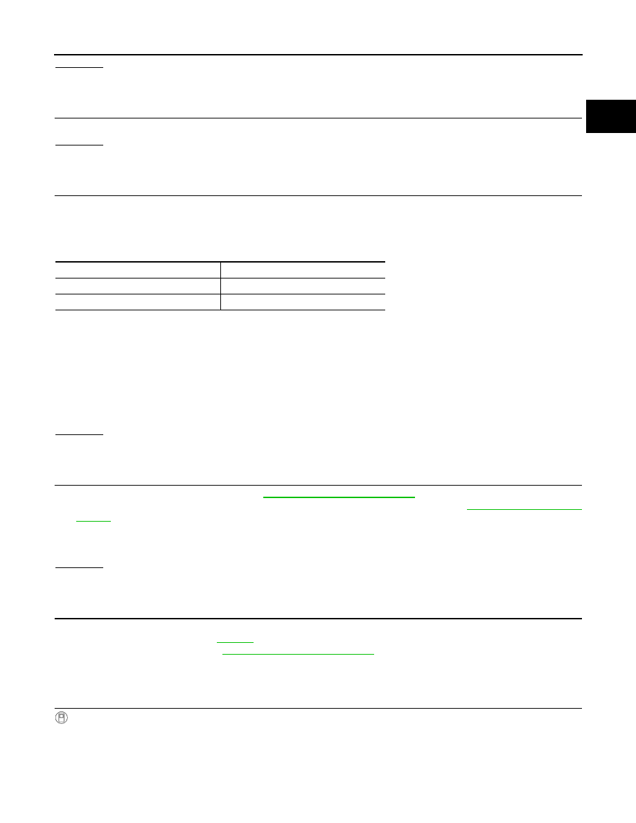
A/F sensor 1

ECM terminal

1

45

2

49

Continuity should exist.

Continuity should not exist.

At idling: Approximately 350 kPa (3.57 kg/cm

2

, 51 psi)

At idling

: 1.0- 4.0 g/s

At 2,500 rpm

: 4.0 - 12.0 g/s 

EC-236

< DTC/CIRCUIT DIAGNOSIS >

[QR25DE]

P0172 FUEL INJECTION SYSTEM FUNCTION

With GST

1. Install all removed parts.

2. Check mass air flow sensor signal in SERVICE $01 with GST.

OK or NG

OK

>> GO TO 7.

NG

>> Check connectors for rusted terminals or loose connections in the mass air flow sensor circuit or

grounds. Refer to 

EC-164, "Component Description"

.

7.

CHECK FUNCTION OF FUEL INJECTOR

With CONSULT

1. Start engine.

2. Perform “POWER BALANCE” in “ACTIVE TEST” mode with CONSULT.

3. Make sure that each circuit produces a momentary engine speed drop.

Without CONSULT

1. Start engine.

2. Listen to each fuel injector operating sound.

OK or NG

OK

>> GO TO 8.

NG

>> Perform trouble diagnosis for 

EC-439

.

8.

CHECK FUEL INJECTOR

1. Remove fuel injector assembly. Refer to 

EM-39, "Removal and Installation"

.

Keep fuel hose and all fuel injectors connected to fuel injector gallery.

2. Confirm that the engine is cooled down and there are no fire hazards near the vehicle.

3. Disconnect all fuel injector harness connectors.

4. Disconnect all ignition coil harness connectors.

5. Prepare pans or saucers under each fuel injector.

6. Crank engine for about 3 seconds.

Check that fuel does not drip from fuel injector.

OK or NG

OK (Does not drip.)>>GO TO 9.

NG (Drips.)>>Replace the fuel injectors from which fuel is dripping. Always replace O-ring with new one.

Refer to 

EM-39, "Exploded View"

.

9.

CHECK INTERMITTENT INCIDENT

Perform 

GI-42, "Intermittent Incident"

.

>> INSPECTION END

At idling

: 1.0 - 4.0 g/s

At 2,500 rpm

: 4.0 - 12.0 g/s

Clicking noise should be heard.

PBIB1986E

P0181 FTT SENSOR

EC-237

< DTC/CIRCUIT DIAGNOSIS >

[QR25DE]

C

D

E

F

G

H

I

J

K

L

M

A

EC

N

P

O

P0181 FTT SENSOR

Component Description

INFOID:0000000009480892

The fuel tank temperature sensor is used to detect the fuel tempera-

ture inside the fuel tank. The sensor modifies a voltage signal from

the ECM. The modified signal returns to the ECM as the fuel temper-

ature input. The sensor uses a thermistor which is sensitive to the

change in temperature. The electrical resistance of the thermistor

decreases as temperature increases.

<Reference data>

*: This data is reference value and is measured between ECM terminal 95 (Fuel tank
temperature sensor) and 112 (ECM ground).

CAUTION:

Never use ECM ground terminals when measuring input/output

voltage. Doing so may result in damage to the ECM's transistor.

Use a ground other than ECM terminals, such as the ground.

On Board Diagnosis Logic

INFOID:0000000009480893

DTC Confirmation Procedure

INFOID:0000000009480894

1.

INSPECTION START

Is it necessary to erase permanent DTC?

YES

>> GO TO 7.

NO

>> GO TO 2.

2.

PRECONDITIONING

If DTC Confirmation Procedure has been previously conducted, always perform the following before conduct-

ing the next test. 

BBIA0545E

Fluid temperature

°C (°F)

Voltage*

V

Resistance

k

20 (68)

3.5

2.3 - 2.7

50 (122)

2.2

0.79 - 0.90

SEF012P

DTC No.

Trouble diagnosis name

DTC detecting condition

Possible cause

P0181

Fuel tank temperature sensor 
circuit range/performance

A)

Rationally incorrect voltage from the 
sensor is sent to ECM, compared with 
the voltage signals from engine coolant 
temperature sensor and intake air tem-
perature sensor.

• Harness or connectors

(The sensor circuit is open or shorted)

• Fuel tank temperature sensor

B)

The comparison result of signals trans-
mitted to ECM from each temperature 
sensor (IAT sensor, ECT sensor, and 
FTT sensor) shows that the voltage 
signal of the FTT sensor is higher/low-
er than that of other temperature sen-
sors when the engine is started with its 
cold state.

• Harness or connectors

(High or low resistance in the FTT 
sensor circuit)

• FTT sensor

EC-238

< DTC/CIRCUIT DIAGNOSIS >

[QR25DE]

P0181 FTT SENSOR

1. Turn ignition switch OFF and wait at least 10 seconds.

2. Turn ignition switch ON.

3. Turn ignition switch OFF and wait at least 10 seconds.

>> GO TO 3.

3.

PERFORM DTC CONFIRMATION PROCEDURE FOR MALFUNCTION A-I

1. Turn ignition switch ON and wait at least 10 seconds.

2. Check 1st trip DTC.
Is 1st trip DTC detected?

YES

>> Go to 

EC-239, "Diagnosis Procedure"

.

NO

>> GO TO 4.

4.

CHECK ENGINE COOLANT TEMPERATURE

With CONSULT

1. Select “COOLAN TEMP/S” in “DATA MONITOR” mode with CONSULT.

2. Check “COOLAN TEMP/S” indication.

With GST

Follow the procedure “With CONSULT” above.
Is “COOLAN TEMP/S” indication less than 60

°C (140°F)?

YES

>> INSPECTION END

NO

>> GO TO 5.

5.

PERFORM DTC CONFIRMATION PROCEDURE FOR MALFUNCTION A-II

With CONSULT

1. Cool engine down until “COOLAN TEMP/S” indication is less than 60

°C (140°F).

2. Wait at least 10 seconds.

3. Check 1st trip DTC.

With GST

Follow the procedure “With CONSULT” above.
Is 1st trip DTC detected?

YES

>> Go to 

EC-239, "Diagnosis Procedure"

.

NO

>> GO TO 6.

6.

PERFORM COMPONENT FUNCTION CHECK (FOR MALFUNCTION B)

Perform component function check. Refer to 

EC-239, "Component Function Check"

.

NOTE:

Use the component function check to check the overall function of the FTT sensor circuit. During this check, a

1st trip DTC might not be confirmed.
Is the inspection result normal?

YES

>> INSPECTION END

NO

>> Proceed to 

EC-239, "Diagnosis Procedure"

.

7.

PRECONDITIONING

If DTC CONFIRMATION PROCEDURE has been previously conducted, always perform the following proce-

dure before conducting the next test.

1. Turn ignition switch OFF and wait at least 10 seconds.

2. Turn ignition switch ON.

3. Turn ignition switch OFF and wait at least 10 seconds.

TESTING CONDITION:

• Before performing the following procedure, do not add fuel.

• Before performing the following procedure, check that fuel level is between 1/4 and 4/4.

• Before performing the following procedure, confirm that battery voltage is 11 V or more at idle.

>> GO TO 8.

8.

PERFORM DTC CONFIRMATION PROCEDURE B

1. Start engine and let it idle for 60 minutes.


Content   ..  414  415  416  417   ..