Nissan Frontier. Manual - part 403


  Index      Nissan     Nissan Frontier (2014 year) - Service and Repair Manual


Search            


Content   ..  401  402  403  404   ..


Nissan Frontier. Manual - part 403


P0117, P0118 ECT SENSOR

EC-183

< DTC/CIRCUIT DIAGNOSIS >

[QR25DE]

C

D

E

F

G

H

I

J

K

L

M

A

EC

N

P

O

1. Turn ignition switch OFF.

2. Disconnect ECM harness connector.

3. Check harness continuity between ECT sensor terminal 2 and ECM terminal 52.

Refer to Wiring Diagram.

4. Also check harness for short to ground and short to power.
OK or NG

OK

>> GO TO 4.

NG

>> Repair open circuit, short to ground or short to power in harness or connectors.

4.

CHECK ENGINE COOLANT TEMPERATURE SENSOR

Refer to 

EC-183, "Component Inspection"

.

OK or NG

OK

>> GO TO 5.

NG

>> Replace engine coolant temperature sensor. Refer to 

CO-23, "Exploded View"

.

5.

CHECK INTERMITTENT INCIDENT

Refer to 

GI-42, "Intermittent Incident"

.

>> INSPECTION END

Component Inspection

INFOID:0000000009480832

ENGINE COOLANT TEMPERATURE SENSOR

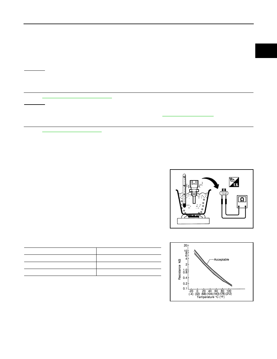
1. Check resistance between engine coolant temperature sensor

terminals 1 and 2 as shown in the figure.

<Reference data>

2. If NG, replace engine coolant temperature sensor.

Continuity should exist.

PBIB2005E

Engine coolant temperature [

°C (°F)]

Resistance (k

Ω)

20 (68)

 2.1 - 2.9

50 (122)

0.68 - 1.00

90 (194)

0.236 - 0.260

SEF012P

EC-184

< DTC/CIRCUIT DIAGNOSIS >

[QR25DE]

P0122, P0123 TP SENSOR

P0122, P0123 TP SENSOR

Component Description

INFOID:0000000009480833

Electric throttle control actuator consists of throttle control motor,

throttle position sensor, etc. The throttle position sensor responds to

the throttle valve movement. 

The throttle position sensor has two sensors. These sensors are a

kind of potentiometer which transform the throttle valve position into

output voltage, and emit the voltage signal to the ECM. The ECM

judges the current opening angle of the throttle valve from these sig-

nals and controls the throttle valve opening angle in response to

driving conditions via the throttle control motor.

On Board Diagnosis Logic

INFOID:0000000009480834

These self-diagnoses have the one trip detection logic.

FAIL-SAFE MODE

When the malfunction is detected, ECM enters fail-safe mode and the MIL lights up.

DTC Confirmation Procedure

INFOID:0000000009480835

NOTE:

If DTC Confirmation Procedure has been previously conducted, always turn ignition switch OFF and wait at

least 10 seconds before conducting the next test.

TESTING CONDITION:

Before performing the following procedure, confirm that battery voltage is more than 10V at idle.

 WITH CONSULT

1. Start engine and let it idle for 1 second.
2. Check DTC.
3. If DTC is detected, go to 

EC-184, "Diagnosis Procedure"

.

 WITH GST

Follow the procedure “WITH CONSULT” above.

Diagnosis Procedure

INFOID:0000000009480836

1.

CHECK GROUND CONNECTIONS

1. Turn ignition switch OFF.

PBIB0145E

DTC No.

Trouble diagnosis name

DTC detecting condition

Possible cause

P0122
0122

Throttle position sensor 
2 circuit low input

An excessively low voltage from the TP 
sensor 2 is sent to ECM.

• Harness or connectors

(The TP sensor 2 circuit is open or shorted.)
(APP sensor 2 circuit is shorted.)

• Electric throttle control actuator

(TP sensor 2)

• Accelerator pedal position sensor

(APP sensor 2)

P0123
0123

Throttle position sensor 
2 circuit high input

An excessively high voltage from the TP 
sensor 2 is sent to ECM.

Engine operation condition in fail-safe mode

The ECM controls the electric throttle control actuator in regulating the throttle opening in order for the idle position to be within +10 
degrees.
The ECM regulates the opening speed of the throttle valve to be slower than the normal condition.
So, the acceleration will be poor. 

P0122, P0123 TP SENSOR

EC-185

< DTC/CIRCUIT DIAGNOSIS >

[QR25DE]

C

D

E

F

G

H

I

J

K

L

M

A

EC

N

P

O

2. Loosen and retighten two ground screws on the body. Refer to 

EC-149, "Ground Inspection"

.

OK or NG

OK

>> GO TO 2.

NG

>> Repair or replace ground connections.

2.

CHECK THROTTLE POSITION SENSOR 2 POWER SUPPLY CIRCUIT-I

1. Disconnect electric throttle control actuator harness connector.

2. Turn ignition switch ON.

3. Check voltage between electric throttle control actuator terminal

2 and ground with CONSULT or tester.

OK or NG

OK

>> GO TO 7.

NG

>> GO TO 3.

3.

CHECK THROTTLE POSITION SENSOR 2 POWER SUPPLY CIRCUIT-II

1. Turn ignition switch OFF.

2. Disconnect ECM harness connector.

3. Check harness continuity between electric throttle control actuator terminal 2 and ECM terminal 47.

Refer to Wiring Diagram.

OK or NG

OK

>> GO TO 4.

NG

>> Repair open circuit.

4.

CHECK THROTTLE POSITION SENSOR 2 POWER SUPPLY CIRCUIT-III

Check harness for short to power and short to ground, between the following terminals.

BBIA0614E

BBIA0616E

Voltage: Approximately 5V

PBIB2604E

Continuity should exist.

ECM terminal

Sensor terminal

47

Electric throttle control actuator terminal 2

81

APP sensor terminal 1

EC-186

< DTC/CIRCUIT DIAGNOSIS >

[QR25DE]

P0122, P0123 TP SENSOR

OK or NG

OK

>> GO TO 5.

NG

>> Repair short to ground or short to power in harness or connectors.

5.

CHECK APP SENSOR

Refer to 

EC-424, "Component Inspection"

OK or NG

OK

>> GO TO 11.

NG

>> GO TO 6.

6.

REPLACE ACCELERATOR PEDAL ASSEMBLY

1. Replace accelerator pedal assembly. Refer to 

ACC-3, "Component"

.

2. Perform 

EC-123, "Accelerator Pedal Released Position Learning"

.

3. Perform 

EC-123, "Throttle Valve Closed Position Learning"

.

4. Perform 

EC-124, "Idle Air Volume Learning"

.

>> INSPECTION END

7.

CHECK THROTTLE POSITION SENSOR 2 GROUND CIRCUIT FOR OPEN AND SHORT

1. Turn ignition switch OFF.

2. Disconnect ECM harness connector.

3. Check harness continuity between ECM terminal 36 and electric throttle control actuator terminal 4.

Refer to Wiring Diagram.

4. Also check harness for short to ground and short to power.
OK or NG

OK

>> GO TO 8.

NG

>> Repair open circuit, short to ground or short to power in harness or connectors.

8.

CHECK THROTTLE POSITION SENSOR 2 INPUT SIGNAL CIRCUIT FOR OPEN AND SHORT

1. Check harness continuity between ECM terminal 38 and electric throttle control actuator terminal 3.

Refer to Wiring Diagram.

2. Also check harness for short to ground and short to power.
OK or NG

OK

>> GO TO 9.

NG

>> Repair open circuit, short to ground or short to power in harness or connectors.

9.

CHECK THROTTLE POSITION SENSOR

Refer to 

EC-187, "Component Inspection"

.

OK or NG

OK

>> GO TO 11.

NG

>> GO TO 10.

10.

REPLACE ELECTRIC THROTTLE CONTROL ACTUATOR

1. Replace the electric throttle control actuator. Refer to 

EM-27, "Exploded View"

.

2. Perform 

EC-123, "Throttle Valve Closed Position Learning"

.

3. Perform 

EC-124, "Idle Air Volume Learning"

.

>> INSPECTION END

11.

CHECK INTERMITTENT INCIDENT

Refer to 

GI-42, "Intermittent Incident"

.

Continuity should exist.

Continuity should exist.


Content   ..  401  402  403  404   ..